Multiple sensor and injector failure codes

Tiny
CSKUDS
  • MEMBER
  • 2008 ALFA ROMEO 159
  • 2.4L
  • 5 CYL
  • TURBO
  • 2WD
  • MANUAL
  • 97,000 MILES
Hi, I have just installed a head gasket and the repair seems fine although it took a couple of attempts. However now I'm getting fault codes p2013, p0095, p0235, p0201, 2, 3 and 4 so all injectors. It starts a little rough with a bit of diesely smoke then ticks over ok, but engine management light is on and there is no acceleration or turbo boost, the boost gauge stays on zero. And the glow plug tips are quite sooted up. I assume its in limp mode.

I have checked all the electrical connections and fuses, all seem fine, I cant see it being a wiring problem as there are so many wires to these multiple sensors and injectors they cant all have broken or failed.

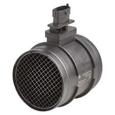
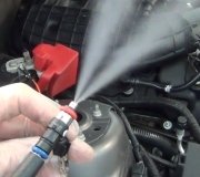
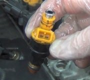
I have done a voltage test with the ignition in the on position but engine not running and I'm getting various readings from the injector connectors between 1.2 and 2.4 volts, each one being different. And I got a reading of 2.4ish volts to the maf and map sensor connectors dropping to about 1.2 as I hold the voltmeter to it, you can just see it drop. I'm not sure what's normal or if the tests have to be done with the engine running but hopefully that will help diagnose. All these things seem to plug directly into the top connector on the ecu, there doesn't appear to be anything in between.

Any help is greatly appreciated, I am well and truly stuck!
Tuesday, January 27th, 2015 AT 10:11 AM

28 Replies

Tiny
CARADIODOC
  • MECHANIC
  • 33,741 POSTS
What you're describing is a typical result of of an electrical problem that can all be related to one or two wires. Many sensors are fed from the same 5.0 volt source, then multiple wires split off and go to each one. A common cause of this is a stretched connector terminal, particularly after a connector has been unplugged. Corrosion can get in there too and often not cause symptoms until the plug is disturbed.

The clue here is a voltage that is changing. Since most sensors are fed with 5.0 volts, if you find less, follow that wire back to the next accessible test point until you find the spot where you DO have 5.0 volts. That is how we narrow down the location of a broken or poor connection.
Was this
answer
helpful?
Yes
No
Tuesday, January 27th, 2015 AT 5:46 PM
Tiny
CSKUDS
  • MEMBER
  • 16 POSTS
Hi, thanks for the response. I tracked the wires back to the ecu. The ecu is getting full power from the battery so that's ok. But it might be dishing it out wrong.
I tried running the engine and disconnecting the injectors and connecting up the multimeter, the reading was around 20 volts sent to each injector from the ecu while running, I assume that voltage is so high because the ecu has detected a lack of fuel in that cylinder (because of the disconnection) and is trying to tell the injector to pump more in.

Would this be correct? If so, the ecu seems to be fine and so does the wires/connections.

So could there be a particular sensor playing up that could cause all these faulty readings by a knock on effect?
Was this
answer
helpful?
Yes
No
Wednesday, January 28th, 2015 AT 2:54 PM
Tiny
CARADIODOC
  • MECHANIC
  • 33,741 POSTS
You can't read injector voltages with a voltmeter. When they turn off, they develop voltage spikes just like an ignition coil does on a gas engine. Your meter is reacting to those spikes.

Fuel metering is controlled by how long the injectors are held open by the Engine Computer. They're typically supplied with 12 volts, then the computer grounds the second terminal for a carefully calculated period of time to hold them open. That time changes to control fuel delivery, and can be viewed as "injector ms" meaning milliseconds, on a scanner that displays live data.
Was this
answer
helpful?
Yes
No
Thursday, January 29th, 2015 AT 8:42 AM
Tiny
CSKUDS
  • MEMBER
  • 16 POSTS
Ok, that's good to know thanks. I cant see where it is going wrong, all the wires run separately into the large connector that plugs into the ecu, nowhere else on the way, I have followed each cable.

So either the connection to the ecu has failed at many points, which I think may be unlikely?

The ecu is being supplied ok by the battery with the full 12 volts, so the fault has to be with the ecu or the main connector to it, so maybe a failing ecu?

Or could it be a single sensor failure that has caused it to go into limp mode and trigger all these other fault codes?
Was this
answer
helpful?
Yes
No
Thursday, January 29th, 2015 AT 11:04 AM
Tiny
CARADIODOC
  • MECHANIC
  • 33,741 POSTS
I don't have a listing for these fault codes. Do you have a description of each one? If there is one that makes reference to one sensor, like the throttle position sensor or a temperature sensor, we can start with that one and take some voltage readings. Since everything was working properly before the repairs were done, it's likely there is going to be a cut wire or a grounded wire.
Was this
answer
helpful?
Yes
No
Thursday, January 29th, 2015 AT 11:17 AM
Tiny
CSKUDS
  • MEMBER
  • 16 POSTS
Yeah sure, the exact descriptions from my manual for each code is: 095 is iat sensor 2 circuit, 201 is injector circuit open cylinder 1, the same for cylinders 2, 3 and 4 (its a 5 cylinder engine, so randomly cylinder 5 is ok), although I also see this code can mean general fault/failure, 235 is turbo/super boost sensor A circuit malfunction and 2013 is Intake Manifold Runner Ctrl Circ High Bank 2.
Hope that can narrow it down. Someone did suggest that the battery might be to blame, it reads 12.2 volts standing and I cant remember exactly, but 14. Something with engine running.

It has been apart a number of times, it did this before, then after taking it a part and putting it back together it was fine, then unfortunately it had to come apart again and the faults have come up again
Was this
answer
helpful?
Yes
No
Thursday, January 29th, 2015 AT 1:01 PM
Tiny
CARADIODOC
  • MECHANIC
  • 33,741 POSTS
I'm familiar with the intake air temperature sensor, so lets start with that one. Unplug the two-wire connector, then measure the voltages on those wires with the ignition switch turned in. You must find 5.0 volts on one of them and 0.2 on the other. Now plug it back in and back-probe through the rubber seal to take the readings again. The ground wire should still have 0.2 volts, but the signal wire should have dropped from 5.0 volts to something between 0.5 and 4.5 volts. Typically you'll find around 3.0 volts.

If you ever find 0.0 volts on the signal wire, there's a break in that wire. If you ever find 5.0 volts on both wires, there's a break in the ground wire.
Was this
answer
helpful?
Yes
No
Thursday, January 29th, 2015 AT 1:17 PM
Tiny
CSKUDS
  • MEMBER
  • 16 POSTS
That's great thanks, its 11pm here though so will have to do it tomorrow, to give me more to check if that passes what should I check next?
Was this
answer
helpful?
Yes
No
Thursday, January 29th, 2015 AT 2:53 PM
Tiny
CARADIODOC
  • MECHANIC
  • 33,741 POSTS
The next step would be to pick another fault code and test the circuit it refers to. I can't find any service literature though to tell you what to look for. The intake air temperature sensor works the same way on almost all cars. That's why I picked that one to start on.
Was this
answer
helpful?
Yes
No
Thursday, January 29th, 2015 AT 6:05 PM
Tiny
CSKUDS
  • MEMBER
  • 16 POSTS
Hi, struggled to get out and do much because of the snow! But I have managed to get some reading from all the sensor connections I can get to.

MAF sensor: 4 points reading 12.3v, 0.01v, 4.97v, 4.97v
MAP sensor: 4 points reading 0.01v, 4.96v, 4.96v, 5.68v
Sensor on entrance to intake manifold (guessing iat sensor): 4 points reading 12.34v, 0.01v, 4.96v and the last one is all over the place fluctuating between 0.01 and 3.3 volts.

So I'm guessing this last wire is the faulty one, with a partial break in the wire, I just need to probe it back now. But are those other readings correct? The earth voltage doesn't seem big enough and I'm not sure what the 12volt readings are all about
Was this
answer
helpful?
Yes
No
Saturday, January 31st, 2015 AT 6:49 AM
Tiny
CARADIODOC
  • MECHANIC
  • 33,741 POSTS
Every intake air temperature sensor I'm familiar with has only two wires or it's incorporated into the mass air flow sensor. 3.3 volts is a typical value on the signal wire but it shouldn't be bouncing around.

Most MAP sensors have only three wires. The signal wire starts out fairly high with the engine not running, but it shouldn't be all the way up to the 5.0 supply voltage. That wire should drop to around 2.0 volts as soon as the engine starts.

What I would do is monitor that IAT wire with the bouncing voltage, and flex the wire harnesses to see if you can find an area that makes it hold steady at 0.0 or 5.0 volts.
Was this
answer
helpful?
Yes
No
Saturday, January 31st, 2015 AT 5:12 PM
Tiny
CSKUDS
  • MEMBER
  • 16 POSTS
Hi, I've just been back out there and managed to get into the ecu connector and had a fiddle with the wires, the wire that was bouncing around now reads 0.01 volts with the ignition on and 3.26 with the engine running solid, it doesn't move around now. But I don't think it was the IAT sensor because I now have an extra error code p2620 - throttle postion output circuit/open!

So I'm guessing the IAT must be built into the MAF sensor.

map ignition on readings: 0.01, 4.97, 4.97, 5.67
engine running readings: 0.00, 4.96, 4.96, 5.73

Maf sensor:
https://www.2carpros.com/images/question_images/199503/original.jpg

maf ignition on readings: 11.99, 0.01, 4.97, 4.97
engine running readings: 13.92, 0.00, 4.96, 4.96

As you can see in the pictures, the connection ports are wide, there are 4 prongs in each port.

And the throttle position sensor readings are:
Ignition on: 12.06, 0.01, 4.97, 0.01
engine running: 14.10, 0.00, 4.96, 3.26

Can you get any information from that? It seemed that wire with the bouncing readings was an earth, only it gets voltage running through it when the engine runs and there already appears to be an earth on that socket, I'm guessing by the readings on the other sensors it should probably read 4.97 or something similar
Was this
answer
helpful?
Yes
No
Sunday, February 1st, 2015 AT 9:46 AM
Tiny
CARADIODOC
  • MECHANIC
  • 33,741 POSTS
I've never seen any of these sensors on any car that have anything other than 5.0 volts applied to them, so all those readings you found higher than that confuse me. Any chance you're using an auto-ranging voltmeter and are overlooking when it switches to the millivolts scale? I hate auto-ranging meters for that reason, and don't own any.

The glaring problem is there's no change in the MAP reading between ignition on and engine running. That can be caused by a disconnected vacuum hose for that sensor, or a break in the signal wire. To verify a break, measure that voltage at the computer like you did, then at the sensor. Both should be exactly the same.
Was this
answer
helpful?
Yes
No
Monday, February 2nd, 2015 AT 9:45 AM
Tiny
CSKUDS
  • MEMBER
  • 16 POSTS
It is manual, set to max 20 volts for every reading. I don't get it myself, but that's what its saying.

Looking at that sensor the 5.67/5.73 reading seams to be the odd one out now, I have all day tomorrow and the weathers not supposed to be too bad so will hopefully get a chance to really get into it. I have checked all the terminals at the ecu though, and I think there was one that read this. So if that's fine, I will go through the other cables but then what else what else should I check? There is no vacuum pipe to the map, it just plugs straight into the inlet manifold

On the plus side, I checked the lambda sensor, ignition on and that does only have 2 connection points and they read 0.01 and 4.97! So I guess that's fine.
Was this
answer
helpful?
Yes
No
Monday, February 2nd, 2015 AT 12:38 PM
Tiny
CSKUDS
  • MEMBER
  • 16 POSTS
Could the 12 volt readings be an error? Could they be an earth wire gone wrong or something like that? Just trying to think of all possibilities
Was this
answer
helpful?
Yes
No
Monday, February 2nd, 2015 AT 12:40 PM
Tiny
CARADIODOC
  • MECHANIC
  • 33,741 POSTS
Since I'm not familiar with your car, let me double-check a few things. Does it use a negative ground, meaning the battery's negative cable is bolted to the engine and body? Do you have your meter's negative probe on ground too?

I don't know much about lambda sensors, but when there's only two wires to a sensor, one is ground and the other is the signal wire. If you understand electrical theory, this will make sense. The ground wire goes back to the computer, then through some monitoring circuitry before it actually gets to ground. That's why you'll find very close to 0.2 volts instead of 0.0 volts on it.

The signal wire is fed 5.0 volts through some sensing circuitry, to the sensor. With the sensor unplugged, creating an open circuit, the full 5.0 volts will be seen at the connector. When the circuit is completed by plugging the sensor back in, some of that 5.0 volts is dropped across the sensing circuitry inside the computer, and the rest is seen at the sensor. The voltage seen at the sensor is dependent on whatever it measures. If that is temperature, the sensor's resistance goes down as the temperature goes up, so the voltage across it will go down at the same time. If it measures something that changes when the engine is running, such as intake manifold vacuum, the voltage has to change at the same time.

Most MAP sensors are plugged directly into the manifold now like you said, to eliminate that hose, but there has to be a change in the signal wire's voltage as soon as the engine starts. The difference here is those will always have more than two wires. In this case the ground and 5.0 volt feed wires will always stay the same, but you have to see a change at the signal wire. When there's no change between start and run, there has to be a break in the signal wire, or the sensor is defective. The only other possibility is no vacuum is getting to the sensor, which only happens when they use that hose, and it has a break in it.
Was this
answer
helpful?
Yes
No
Monday, February 2nd, 2015 AT 1:33 PM
Tiny
CSKUDS
  • MEMBER
  • 16 POSTS
Ok, my mistake. I disconnected the sensor to read it when it was running, I will probe the wires tomorrow to get a reading when its plugged in and running.

It does use a negative ground, the negative terminal is grounded to the bodywork just beneath it, there are no other leads going anywhere else from the negative terminal.

The meters negative is on the battery negative terminal
Was this
answer
helpful?
Yes
No
Monday, February 2nd, 2015 AT 2:11 PM
Tiny
CSKUDS
  • MEMBER
  • 16 POSTS
Ok, bad development. I probed the wires and got readings while it was running. The bad news is I then switched it off but left the ignition on, removed the top ecu connector and got readings from all the pins in there, unfortunately when I finished and reconnected it all up I went to start it and its all over the place. The boost gauge use to be non respondent, now it flickers up and down wildly, the engine management light is flickering all the time, the throttle is continuously opening and closing and loads of error messages come up on the dash display. I plugged in my code reader and it says connection error so gives me nothing. It wont start either.

I re-took the voltage readings while it was doing this, both the 12 volt readings have dropped to 6 volts and 4 of the smaller 1.8/2.4 ish volt readings have dropped half a volt, the rest remain the same (there are 60 pins).

Here are the sensor readings before it went crazy:

Map sensor ignition on : 0.01, 4.97, 4.97, 5.67
engine running probed: 0.01, 2.58, 3.2, 0.90

Maf sensor ignition on: 11.99, 0.01, 4.97, 4.97
Engine running probed: 9.03, 0.01, 2.30, 1.48

So they have dropped and appear to be functioning I think, maybe it was an ecu error after all, and I have just tipped it over the edge somehow. It has been off road for around 8 months.

So is there anything I can do to rectify this? Does it have to be sent off for repair, or could something else be to blame? Thanks for all your help with this by the way
Was this
answer
helpful?
Yes
No
Tuesday, February 3rd, 2015 AT 9:27 AM
Tiny
CARADIODOC
  • MECHANIC
  • 33,741 POSTS
To have many voltages change, especially when disconnecting and reconnecting the plug, is reminiscent of the huge problem GM had with their Engine Computers in the late '80s and early '90s. I suspect, by the way they acted, they developed numerous bad solder connections inside. We used to see that all the time on tv modules that were machine-soldered. A real lot of engine performance problems were solved by replacing those GM computers, and it's a big reason why so many mechanics fall back on computers as the big suspects now.

If you can get the circuit board out of the housing, a local tv repairman can inspect it visually for broken connections. Also look closely at the connector pins for signs of corrosion. Terminals in connectors can stretch too and make poor contact, but that normally isn't a problem with Engine Computer terminals because they're pretty high-quality and they don't get taken apart very much.
Was this
answer
helpful?
Yes
No
Tuesday, February 3rd, 2015 AT 5:17 PM
Tiny
CSKUDS
  • MEMBER
  • 16 POSTS
Hi, there's been a few developments. I got the lid off the ECU but couldn't get the circuit board out. So sent it off to be repaired, they sent me a reconditioned ecu, I plugged it in and there was no change! Still all over the show. So I checked all the fuses again, I found a blown fuse, replaced it and it stabilised again, so it doesn't fluctuate any more. However despite the new ECU, the original several errors are still there.

So I'm stuck, I cant see why it just doesn't work. The ecu is fine. The wires appear to have continuity and the sensors respond to the engine running.
What else is there?
Was this
answer
helpful?
Yes
No
Thursday, February 12th, 2015 AT 3:18 PM

Please login or register to post a reply.

Sponsored links