OK you've made me do a lot of research, . I asked you if you had vacuum hook up to the transformation, you fail to respond only telling me " I t has only the linkage from the shifter to transmission and the speed cable" which is incorrect, For your benefit, I will explain to you, the vacuum control system to your transmission;
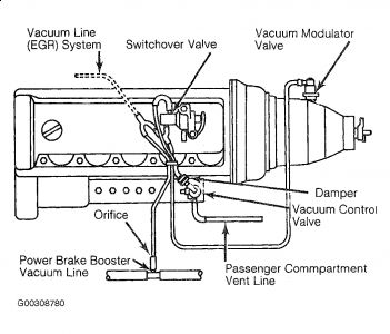
VACUUM CONTROL SYSTEM Vacuum is tapped at vacuum line for power brake booster and is routed to switchover valve, a vacuum distributor, (by way of an orifice) to vacuum control valve and distributor. The switchover valve is actuated by a regulating system for shifting of 1st gear when moving off. Switchover valve is interconnected into vacuum control line from vacuum control unit. In idle throttle position, vacuum control valve connects vacuum line leading to vacuum control unit, while bypassing vacuum switchover valve. As a result, full pump vacuum of approx. 11 in. Hg. reacts on vacuum control and transmission stays in 2nd gear. During acceleration, switchover valve connects vacuum control unit with vacuum control valve. Depending on position of accelerator pedal, vacuum control valve establishes a vacuum value of approx. 0-6 in. Hg. This vacuum reduction is the signal to transmission to shift to 1st gear when moving off. California models also have a vacuum operated EGR (Exhaust Gas Recirculation) system with additional switchover valves. These switchover valves are also connected to vacuum control system, but they are only controlling EGR requirements.
the following is a procedure to make sure the transmission has vacuum.
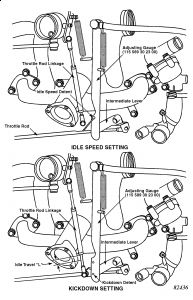
VACUUM CONTROL SYSTEM Vacuum Control Valve Pull off vacuum line to transmission and connect vacuum tester (116 589 25 21 00) to "Y" connector. See Fig. 1 . Disconnect connecting rod at ball head. Start engine and increase speed to approximately 1300 RPM. See Fig. 2 . Place adjusting roller (916 589 00 21 00) on vacuum control valve. Raise lever on vacuum control valve until it contacts roller. Vacuum must read 11 to 17 in. Hg. If this value cannot be obtained, vacuum control valve must be replaced. Vacuum Switchover Valve With engine at idle, pull control line from switchover valve and connect vacuum tester. Run engine at idle. After about 1 minute, vacuum reading should be between 11-14 in. Hg. If vacuum reading is off, check to see if either suction or control line at switchover valve or vacuum control valve have been switched. Check for vacuum leaks (including central locking system, key start system etc.) Accelerate until switchover valve is actuated, vacuum should drop to 4-6 in. Hg. If not check orifice in distributor for being plugged or presence of a vacuum leak. If switchover valve is leaking replace unit.
it is also critical that your throttle linkage is adjusted properly, here's the procedure to ensure that;
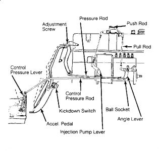
TRANSMISSION THROTTLE ROD Turn rotary knob of cable control for idling speed adjustment completely to the right. Disconnect throttle rod linkage, throttle rod, and accelerator rod from intermediate lever. Attach adjusting gauge with idle speed detent to intermediate lever. With throttle valve against idle speed stop, and throttle linkage pulled back, adjust throttle rod linkage length for a free fit on ball socket of intermediate lever. Push control lever to idle position, then adjust accelerator rod length for a free fit over ball socket on intermediate lever. See Fig. 1 . Fig. 1: 240D Throttle Rod Adjustment Remove adjusting gauge idle detent from intermediate lever. Press accelerator pedal to kick down position, adjusting gauge full-throttle detent should fit freely into intermediate lever. If not, adjust length of accelerator rod for a free fit. With adjustments made, check that travel "L", of throttle rod linkage, from full throttle position to kick down position is approximately .236" (6 mm). If not, adjust ball socket in oblong hole of intermediate lever. When adjustments are correct, remove adjusting gauge.
also makes sure the shift linkage is adjusted properly;
SHIFT LINKAGE Floor Shift Disconnect shift rod from selector lever. Place selector lever and control lever in "N" position. Make sure there is approximately .04" (1 mm) clearance between control lever and "N" position stop on console. Adjust shift rod length for a free fit in selector lever. Tighten lock nut.
I will also give you the procedure for removal and installation to make sure you did it correctly;
REMOVAL - 240 SERIES Disconnect negative battery terminal and raise vehicle on a hoist. Disconnect fluid filter tube from oil pan and remove torque converter drain fluid from transmission assembly. Disconnect fluid cooler lines from transmission case, then remove clips attaching lines to transmission and engine. Loosen bolts attaching center support bearing to body tunnel, but do not remove at this time. Loosen clamping nut on front drive shaft section, then remove mounting bracket for front exhaust pipe. Remove two bolts attaching transmission mount to rear crossmember, then disconnect mount from transmission. Disconnect selector rod from range selector lever on transmission and place lever in "P" position. Disconnect speedometer driven gear and cable, kickdown switch wire, control pressure lever, and leads to neutral safety switch. Disconnect front drive shaft from transmission flanges, living adapter plate attached to drive shaft. Slide drive shaft toward rear as far as possible and position out of way. Disconnect vacuum line from vacuum modulator unit, and remove clamp retaining vacuum line to transmission. Remove access plate from front of converter housing, then remove bolts attaching torque converter to drive plate. Position jack under transmission assembly. Remove transmission-to-engine attaching bolts. Move transmission rearward until torque converter hub clears drive plate and lower assembly form vehicle. Withdraw torque converter from transmission.
INSTALLATION Reverse removal procedure and note the following: When installing torque converter in transmission, lubricate torque converter tangs, turbine and stator shaft splines with molykote paste. When properly installed, distance between front face of transmission and converter mounting lugs should be more than .16" (4 mm). After installation, adjust transmission control linkage and fill transmission with fluid.
furthermore, I will give you the diagnostic procedure to try to figure out what is wrong with transmission;
TROUBLE SHOOTINGTRANSMISSION SLIPS IN ALL SELECTOR LEVER POSITIONS Incorrect modulating pressure. Modulating pressure control valve sticking. Intake manifold-to-vacuum modulator vacuum line plugged. Working pressure control valve sticking. Defective primary pump.
TRANSMISSION GRABS OR VEHICLE SHAKES WHEN STARTING OFF Incorrect modulating pressure. Check vacuum modulator for presence of fluid; if transmission fluid is found, replace modulator; if fuel is found, check and adjust carburetor or fuel injection system.
TRANSMISSION SLIPS IN 2ND GEAR OR SHIFTS FROM 1ST TO 3RD GEAR Center band control valve sticking or worn. Center band piston sealing ring worn or damaged. Center band worn or damaged. Bleed valves in front clutch supporting flange leaking.
TRANSMISSION SLIPS WHEN SHIFTING FROM 2ND TO 3RD OR FROM 3RD TO 4TH GEARTRANSMISSION SLIPS IN 4TH GEAR, NO 1ST GEAR ENGINE BRAKING Sealing bushings on pipes of valve body worn or damaged. Rear clutch defective.
TRANSMISSION SLIPS IN 1ST & 2ND WHEN STARTING OFF Rear band badly worn or damaged. Incorrect rear band pressure pin.
TRANSMISSION SLIPS IN ALL GEARS Incorrect modulating pressure. Modulating pressure control valve worn or sticking. Modulating pressure relief valve worn, dirty or sticking.
NO POSITIVE ENGAGEMENT IN REVERSE Front band out of adjustment. Sealing ring on rear band piston worn or damaged. One-way roller clutch in gear assembly worn or damaged.
ROUGH JERK WHEN ENGAGING "D" Engine idle speed too high. Modulating and/or working pressure incorrect. Leak in vacuum modulator vacuum line. Pressure receiving piston in extension housing worn, damaged, or installed incorrectly. Feed bore in pressure receiving piston plugged.
NOTE: If a rough jerk results when shifting for short periods back and forth between "N" and "D", it is because the pressure receiver requires approximately 2 seconds to operate.
ROUGH JERKS WITH CHANGING GEARS Incorrect modulating pressure. Incorrect working pressure. If working pressure is too high, replace valve body assembly. Vacuum line to vacuum modulator leaking. Control pressure linkage out of adjustment. Control valve converter adjustment incorrect.
NO UPSHIFTS Worn or damaged governor assembly. Valve body assembly dirty and causing valves and springs to stick. Incorrect governor pressure.
UPSHIFTS ONLY IN UPPER SPEED RANGE Control pressure linkage out of adjustment. Governor assembly worn or damaged. Control pressure control valve inoperable. Propeller shaft flange retaining nut loose.
UPSHIFTS ONLY IN LOWER SPEED RANGE Clamping screw for control pressure lever on transmission loose. Control pressure linkage out of adjustment. Throttle valve out of adjustment. Defective governor causing high governor pressure.
NO KICKDOWN SHIFTS Fuse for power supply to solenoid valve blown. Defective solenoid valve. Clamping screw for control pressure lever on transmission loose. Kickdown control valve in valve body worn or sticking.
NO BRAKE SHIFTS (4-3 AND 3-2)Control pressure out of adjustment. Make brake shaft piston operable and exchange shift valve housing, if required.
DOWNSHIFT WITHOUT USING KICKDOWN SWITCH Check kickdown solenoid valve and "O" ring. Check kickdown solenoid switch and replace if bad (stuck down or open). Check control pressure valve.
next time don't try to be too smart and just answer the questions, because I hate turn into Dr. House.
Monday, November 30th, 2009 AT 10:18 AM