Hi dpetrow,
Here are the diagnostics for the trouble codes.
DTC P0400: EGR FLOW MALFUNCTION
Condition
DTC is set when intake manifold pressure is to high or to low when EGR is turn on and off.
Possible causes are:
"� EGR valve malfunction.
"� EGR boost sensor malfunction.
"� EGR boost solenoid valve malfunction.
"� Restricted exhaust system.
"� Faulty Powertrain Control Module (PCM).
"� Short circuit in wiring harness.
Diagnosis & Repair Procedure
1. Perform DTC confirmation procedure. Check for DTCs during KOEO or KOER self-test. If DTC P0400 is present, go to next step. If DTC P0400 is not present, problem is intermittent.
2. Check EGR boost solenoid valve connector connection. Repair as necessary and check for any other DTC during KOEO or KOER self-test. If any other DTCs are present, go to appropriate test. If no other DTC is present, go to next step.
3. Check for vacuum leaks in hoses connected to MAF sensor, hoses connected to throttle body, intake manifold gasket, PCV system, other vacuum hoses (disconnected) or loose engine dipstick. Also check for exhaust leaks at flanges or gaskets. Repair as necessary and go to step 17 . If no leaks are found, go to next step.
4. Using compression gauge, check cylinder compression. Minimum cylinder compression should be 119 psi (8.4 kg/cm2 ) at 300 RPM and maximum difference between cylinders should be 28 psi (2.0 kg/cm2 ). If cylinder compression is not okay, repair engine as necessary and go to step 17 . If compression is okay, go to next step.
5. Turn ignition on. Listen for click (initialization noise) from EGR valve. EGR valve initialization is closing action of EGR valve before and after engine is turn on and off. If noise can be heard, go to step 11 . If noise cannot be heard, go to next step.
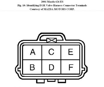
6. Turn ignition off. Disconnect EGR valve connector. Turn ignition on. Measure voltage between ground and EGR valve harness connector terminals "C" (Red/Black wire) and "D" (Red/Black wire), individually. If more than 10.5 volts is present, go to next step. If 10.5 volts or less are present, repair appropriate open circuit. Go to step 17 .
7. Turn ignition off. Measure resistance between EGR valve connector terminals "C" (Red/Black wire) and terminals "A" (Red/Yellow wire) and "E" (Green wire),
individually. See Fig. 10 . Also measure resistance between EGR valve connector terminals "D" (Red/Black wire) and terminals "B" (Pink/Black wire) and "F" (Orange/Black wire), individually. Resistance for each measurement should be about 22 ohms. If resistance is as specified, go to next step. If resistance is not as specified, replace EGR valve and go to step 17 .
8. Disconnect PCM connector. Check for damaged or corroded PCM connector terminals. Repair as necessary, and go to step 17 . If connector terminals are okay, go to next step.
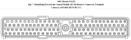
9. Leave ignition off and EGR valve harness connector disconnected. Measure resistance between PCM harness connector terminals and corresponding terminal at EGR valve harness connector. See Fig. 7 . See EGR CIRCUIT IDENTIFICATION table. If resistance is less than 5 ohms, go to next step. If resistance is 5 ohms or more, repair appropriate open circuit. Go to step 17 .
EGR CIRCUIT IDENTIFICATION
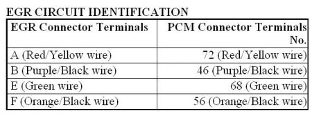
10 . Leave ignition off and EGR valve disconnected. Measure resistance between PCM harness connector terminals No. 46 (Pink/Black wire), 56 (Orange/Black wire), 68 (Green wire) and 72 (Red/Yellow wire), and terminals No. 51 (Black/Blue wire), 91 (Black/Yellow wire) and 103 (Black/Red wire), individually. Measure resistance between PCM harness connector terminals No. 46 (Pink/Black wire), 56 (Orange/Black wire), 68 (Green wire) and 72 (Red/Yellow wire), and terminals No. 71 (Red/Black wire), 90 (Gray/Red wire) and 97 (Red/Black wire), individually. If each measurement is more than 10 k/ohms, replace EGR valve and go to step 17 . If any measurement is 10 k/ohms or less, go to next step.
11. Turn ignition off. Disconnect EGR boost solenoid valve connector. Turn ignition on. Measure voltage between EGR boost solenoid valve harness connector Red/Black terminal and chassis ground. If more than 10.5 volts is present, go to next step. If 10.5 volts or less are present, repair open circuit. Go to step 17 .
12. Turn ignition off. Measure resistance between EGR boost solenoid valve connector terminals. If resistance is 30-70 ohms, go to next step. If resistance is not 30-70 ohms, replace EGR boost solenoid valve and go to step 17 .
13. Disconnect PCM connector. Check for damaged or corroded PCM connector terminals. Repair as necessary, and go to step 17 . If connector terminals are okay, go to next step.
14. Measure resistance between PCM harness connector terminal No. 98 (White/Red wire) and EGR boost solenoid valve harness connector White/Red wire terminal. See Fig. 7 . If resistance is less than 5 ohms, go to next step. If resistance is 5 ohms or more, repair open White/Red wire. Go to step 17 .
15. Measure resistance between PCM harness connector terminals No. 98 (White/Red wire), and terminals No. 51 (Black/Blue wire), 91 (Black/Yellow wire) and 103 (Black/Red wire), individually. See Fig. 7 . Measure resistance between PCM harness connector terminals No. 98 (White/Red wire), and terminals No. 71 (Red/Black wire), 90 (Gray/Red wire) and 97 (Red/Black wire), individually. If each measurement is more than 10 k/ohms, go to next step. If any measurement is 10 k/ohms or less, repair appropriate circuit and go to step 17 .
16. Reconnect PCM and EGR boost solenoid valve connections. Disconnect vacuum hose, located between EGR boost sensor solenoid valve and intake manifold, from EGR boost solenoid valve. Connect vacuum pump to EGR boost solenoid valve and apply 10 in. Hg to EGR boost solenoid valve. Disconnect vacuum hose, located between EGR boost solenoid valve and EGR boost sensor, from EGR boost sensor. Ensure vacuum hose is not damaged. Repair as necessary. If vacuum hose is okay, install vacuum gauge to end of vacuum hose. Turn ignition on. Backprobing, momentarily connect a fused jumper wire between PCM connector terminal No. 98 (White/Red wire) and ground. Again apply 10 in. Hg to EGR boost solenoid valve. Again, momentarily connect a fused jumper wire between PCM connector terminal No. 98 (White/Red wire) and ground. Turn ignition off. If vacuum signal is indicated (at any time), problem is intermittent. If vacuum signal is not indicated, replace EGR boost solenoid valve and go
to next step.
17. Reconnect all connections. Turn ignition on. Clear DTCs. Start engine. Using scan tool, perform OBD II drive mode. Using scan tool, access DIAGNOSIS MONITORING TEST RESULTS in GENERIC OBD II FUNCTIONS. Monitor TEST #10:4C:31 and #10:4C:B1. If measured value is within specification, replace PCM and go to next step. On vehicles equipped with immobilizer system, reprogram ignition key identification numbers. If measured value is not within specification, go to next step.
18. Perform DTC confirmation procedure. Check for DTCs. If any other DTC is present, go to appropriate test.
SPONSORED LINKS
Sunday, October 31st, 2010 AT 2:12 PM