Good evening.
Do you have any codes set for this issue? It is a common problem but needs to be confirmed.
It usually sends a 545 code to the ECM.
Roy
Circuit/System Description
The steering column shaft torque sensor is a 5-volt dual analog inverse signal device which is used to sense steering direction and the amount of torque being applied to the steering column shaft when the steering wheel is turned. The valid signal voltage range of the sensor is 0.25-4.75 volts. When applying torque to the steering column shaft during a right turn, the sensors signal 1 voltage increases, while the signal 2 voltage decreases within the valid signal voltage range. When applying torque to the steering column shaft during a left turn, the sensors signal 1 voltage decreases, while the signal 2 voltage increases within the valid signal voltage range.
After replacing the steering column or power steering control module (PSCM), the steering wheel torque and position sensors must be calibrated.
Conditions for Running the DTC
C0545 00
Engine running
Steering column shaft torque input is present.
C0545 4B
The ignition is ON.
Conditions for Setting the DTC
C0545 00
The torque sensors signal 1 and signal 2 voltages are less than 0.25 volts, or greater than 4.75 volts.
C0545 4B
The PSCM has not undergone the torque sensor calibration procedure.
Action Taken When the DTC Sets
DTC is stored in memory.
The DIC displays the POWER STEERING warning message.
No steering assist is provided.
Conditions for Clearing the DTC
C0545 00, C0545 4B
A current DTC will clear on the next malfunction-free ignition cycle.
A history DTC will clear after 100 consecutive malfunction-free ignition cycles.
Diagnostic Aids
If the PSCM continues to set a history DTC C0545 replace the steering column before replacing the PSCM. Some steering columns may have an intermittent internal wiring condition causing the history DTC C0545.
If the Steering torque or position sensor calibrations are incorrect the customer may complain of steering effort that is easier in one direction than the other. Performing the steering torque and position sensor calibrations procedure will correct this issue.
Reference Information
Schematic Reference
Power Steering Schematics ()
Connector End View Reference
Component Connector End Views (See: Vehicle > Connector Views)
Description and Operation
Power Steering System Description and Operation (EPS) ()Power Steering System Description and Operation (HPS) ()
Electrical Information Reference
Circuit Testing (See: Vehicle > Component Tests and General Diagnostics)
Connector Repairs (See: Vehicle > Component Tests and General Diagnostics)
Testing for Intermittent Conditions and Poor Connections (See: Vehicle > Component Tests and General Diagnostics)
Wiring Repairs (See: Vehicle > Component Tests and General Diagnostics)
Scan Tool Reference
Control Module References (See: Vehicle > Programming and Relearning) for scan tool information
Special Tools
EL-47564 Power Steering Control Module (PSCM) Test Harness
Circuit/System Verification
C0545 00
Ignition ON, observe the scan tool Torque Sensor Signal 1 and 2 parameters. With the steering wheel at rest both readings should be at 2.5 V. While turning the steering wheel from side to side the readings should stay between 0.25-4.75 V and change in opposite directions of each other.
C0545 4B
Verify that DTC C0545 4B is not set.
If the DTC is set, perform the Torque Sensor Calibration procedure. If the DTC resets, replace the PSCM.
Steering torque and position sensor calibrations
1. Center the steering wheel.
Important: After centering the steering wheel, remove hands and other objects from the steering wheel and ensure the suspension is relaxed and no bias, or uneven force is being applied to the steering system.
2. Using the scan tool Perform the Steering Position Sensor Calibration procedure.
3. Using the scan tool Perform the Torque Sensor Calibration procedure.
4. Turn the steering wheel until it stops in each direction.
Circuit/System Testing
C0545 00
1. Disconnect the X3 harness connector at the power steering module assembly.
2. Connect the EL-47564 Power Steering Control Module (PSCM) Test Harness.
3. Ignition OFF, test for less than 2 ohm between the low reference circuit terminal E and ground.
If greater than the specified range, replace the power steering control module.
4. Ignition ON, test for 4.8-5.2 V between the 5 V reference circuit terminal B and ground.
If less than the specified range, replace the power steering control module.
5. Install a 3A fused jumper wire between the signal circuit terminal F and the 5V reference circuit terminal B. Verify the scan tool Torque Sensor Signal 1 is greater than 4.8V.
If less than the specified value, replace the power steering control module.
6. Install a 3A fused jumper wire between the signal circuit terminal C and the 5V reference circuit terminal B. Verify the scan tool Torque Sensor Signal 2 is greater than 4.8V.
If less than the specified value, replace the power steering control module.
7. If all circuits test normal, test or replace the steering column.
Repair Instructions
Perform the Diagnostic Repair Verification (See: A L L Diagnostic Trouble Codes ( DTC ) > Verification Tests) after completing the diagnostic procedure.
Steering Column Replacement (Hydraulic Power Steering) (See: Steering Column > Removal and Replacement > Steering Column Replacement (Hydraulic Power Steering))Steering Column Replacement (Electronic Power Steering) (See: Steering Column Removal and Replacement > Steering Column Replacement (Electronic Power Steering))
Control Module References (See: Vehicle > Programming and Relearning) for PSCM replacement, setup, and programming
Sensor replacement
Steering Wheel Position Sensor Replacement
Tools Required
J 42640 Steering Column Anti-Rotation Pin
Removal Procedure
Important: If replacing the steering wheel position sensor, the new sensor MUST come with a locating pin installed. If a locating pin is not installed, return and reorder a new steering wheel position sensor. Do not apply force to the steering wheel position sensor in a sideways direction.
When reusing the steering wheel position sensor you must install a locating pin before removing it from the steering column. If the steering wheel position sensor loses its correct position it must be discarded.
The locating pin diameter must be in the range of 1.0-2.0 mm.
ImageOpen In New TabZoom/Print
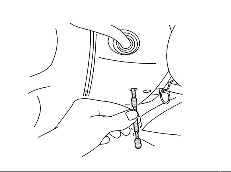
1. Set the front wheels in the straight-ahead position and install anti-rotation pin J 42640 in the steering column lower access hole.
ImageOpen In New TabZoom/Print
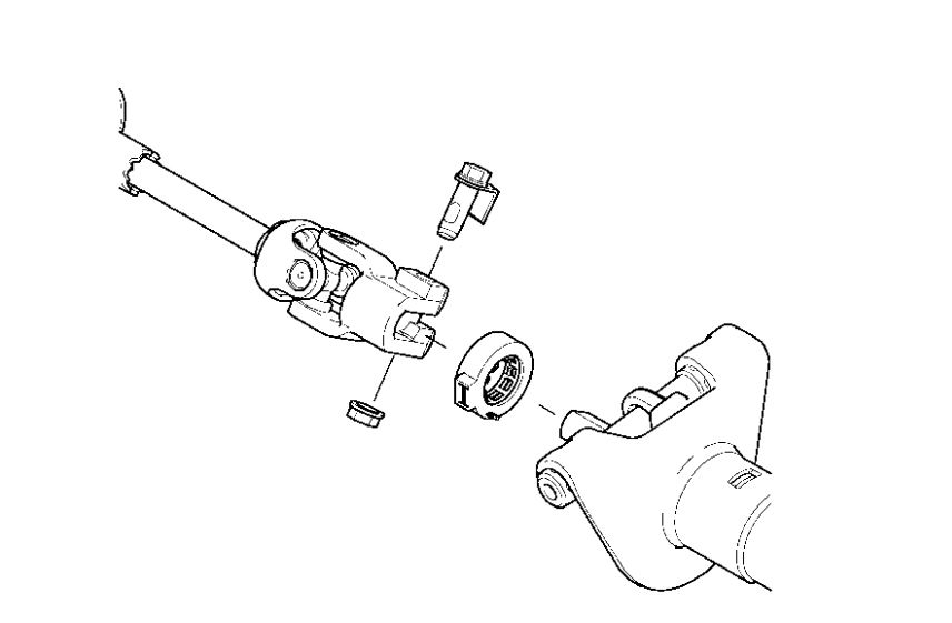
2. Disconnect the intermediate steering shaft from the steering column. Refer to Intermediate Steering Shaft Replacement (See: Steering Column > Removal and Replacement > Intermediate Steering Shaft Replacement).
3. Disconnect any electrical connectors as needed.
4. Remove the steering wheel position sensor.
Images (Click to make bigger)
Monday, March 30th, 2020 AT 3:52 PM