Hi rubinshonda,
When it happens mostly with headlighgts on, it most probably is due to electrical faults and could possibly be a bad ground for the circuit. The troubleshooting procedure might be able to help solve the problem.
"D4" Indicator Light Circuit Troubleshooting (Honda)
1. Turn ignition on. If "D4" indicator light illuminates and remains on, go to next step. If "D4" indicator light does not remain on and turns off after 2 seconds, system is okay. If "D4" indicator light does not illuminate, go to step 4 .
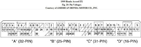
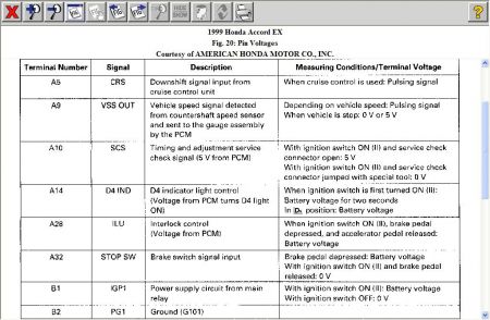
2. Turn ignition off. Disconnect 32-pin PCM harness connector "A". See Fig. 20 . Turn ignition on. Check for voltage between ground and 32-pin PCM harness connector "A", terminal No. 14 (Blue/Red wire). If voltage is present, repair short to voltage in Blue/Red wire between PCM and instrument cluster. If voltage is not present, go to next step.
3. Turn ignition off. Reconnect 32-pin PCM harness connector "A". Turn ignition on. Shift to any gear position except "D4". Measure voltage (backprobe) between ground and 16-pin PCM harness connector "D", terminal No. 9 (Yellow wire). If voltage is present, replace PCM or instrument cluster. If voltage is not present, check Yellow wire for short to ground. Repair as necessary. If no problem is found, replace A/T gear position switch.
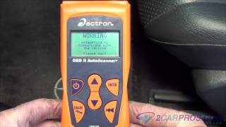
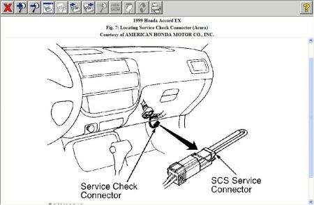
4. Ensure scan tool is not connected to Data Link Connector (DLC). See Fig. 7 . Shift to "D4" position. If "D4" indicator light does not illuminate, go to next step. If "D4" indicator light illuminates, check for loose PCM harness connections. Replace PCM with a known-good unit if necessary and retest.
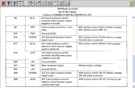
5. Turn ignition off. Disconnect 25-pin PCM harness connector "B". Using DVOM, check for continuity between ground and 25-pin PCM harness connector "B", terminals No. 20 and 22 (Brown/Black wires). See Fig. 20 . If continuity is present, go to next step. If continuity is not present, repair open or poor connection in appropriate Brown/Black wire.
6. Turn ignition on. Measure voltage at 25-pin PCM harness connector "B" between terminals No. 1 (Yellow/Black wire) and No. 22 (Brown/Black wire), and then between terminals No. 9 (Yellow/Black wire) and No. 20 (Brown/Black wire). If battery voltage is present, go to next step. If battery voltage is not present, repair open or short in appropriate Yellow/Black wire between PCM and PGM-FI relay.
7. Turn ignition off. Reconnect PCM harness connector. Connect DVOM (backprobe) between 25- pin PCM harness connector "B", terminal No. 14 (Blue/Red wire) and terminals No. 20 or 22 (Brown/Black wires). Turn ignition on. Voltage should be present for 2 seconds. If DVOM indicates voltage as specified, check for open or short in Blue/Red wire between PCM and gauge assembly. Repair as necessary. If no problem is found, repair faulty "D4" indicator light bulb or gauge assembly printed circuit board. If no voltage was present, go to next step.
8. Turn ignition off. Disconnect 32-pin PCM harness connector "A". Check Blue/Red wire for continuity between 32-pin PCM harness connector "A", terminal No. 14 and gauge assembly harness 16-pin connector terminal No. 3. If continuity is present, check for loose PCM harness connectors or faulty A/T gear position switch. Repair as necessary. If no problem is found, replace PCM with a known-good unit and retest. If continuity is not present, repair open in Red/Blue wire.
Sunday, January 18th, 2009 AT 12:07 AM