TEST Z: INTERMITTENT
Diagnostic Aids
Perform this test when instructed during QUICK TEST or if directed by other test procedures. This system test is intended to diagnose and isolate intermittent concerns for the following:
All engine control sub-systems.
Vehicles with coil pack ignition systems.
The intermittent test table is used to determine which test to perform for the suspect circuit. See INTERMITTENT TEST table. Corresponding Parameter Identification (PIDs) for each circuit are listed. Some circuits do not have an associated PID and can be measured with a Digital Volt-Ohmmeter (DVOM). If vehicle has coil pack ignition system with a no-start condition, perform ignition test. Go to step 50).
1) Direction For Intermittent Diagnostic Path
There are 2 main procedures used in this system test to isolate and repair an intermittent concern. One procedure uses the Rotunda Distributorless Ignition System (DIS) Tester (007-00075) and the other uses a scan tool and a Digital Volt-Ohmmeter (DVOM). The distributorless ignition system tester is used on vehicles coil pack ignition systems. If vehicle has a ignition concern and is equipped with coil pack ignition, go to step 50). If vehicle is not as specified, go to next step.
2) Perform PCM Reset Procedure
If PCM reset produce has already been performed, go to next step. If PCM reset procedure has not been performed, perform PCM RESET procedure under SELF-DIAGNOSTIC SYSTEM. Ensure freeze frame data has been recorded before resetting PCM. After performing PCM reset procedure, go to next step.
3) Select PIDs Related To Symptom
Scan tool and a list of PIDs must be used to indicate area of fault. Obtain symptom from customer description. Use REFERENCE VALUE SYMPTOM table and REFERENCE VALUE/PID MEASUREMENT SIGNAL table in PIN VOLTAGE/PID VALUE CHARTS article to identity PIDs that relate to symptom. Make a list of symptom related PIDs and go to next step.
4) Symptom Verification
Path to symptom verification is optional, but is recommended for the following reasons:
If vehicle is in for a repeat repair.
No DTCs present.
Customer has difficulty describing symptom.
If symptom needs to be verified, go to next step. If symptom is known and does not need to be verified, go to step 11).
5) Note All Available Data To Aid In Symptom Verification
Collect as much data as possible to aid in determining intermittent fault area. Note any freeze frame data that was recorded in step 2). Note any Continuous Memory DTCs that were present prior to performing PCM RESET in step 2). Also, obtain any information from customer that would aid in determining fault area. Go to next step.
NOTE:A road test may be necessary to recreate conditions that originally caused DTC to set.
6) Attempt To Recreate Symptom
Using scan tool, select and monitor PIDs displayed in freeze frame data (if available) and PIDs on list that was developed in step 3). Using freeze frame data recorded earlier, recreate conditions described by each freeze frame PID. Pay particular attention to ECT LOAD, RPM and VSS PIDs. Also use any information available from customer to aid in producing conditions for recreating symptom. When symptom occurs, press trigger on scan tool to begin recording. Refer to scan tool instruction manual for recorder function operation. If symptom is reproduced, go to step 11). If symptom cannot be reproduced, go to next step.
NOTE:PIDs for PCM outputs in pin voltage/PID value charts in PIN VOLTAGE/PID VALUE CHARTS article represent commanded values only. Circuit measurements made with DVOM indicate actual output status. If circuit measurement made with a DVOM differs from scan tool PID value, a circuit fault may be indicated. PIDs for PCM inputs that differ from circuit measurements made with a DVOM indicate a possible PCM fault.
7) Recreate Symptom Using Intermittent Road Test
The intermittent road test procedure is the last attempt to locate area of concern before physically disturbing vehicle circuits. Road test is a set of instructions for monitoring PID values or making circuit measurements with a DVOM. Procedure is performed under 4 conditions, Key On Engine Off (KOEO), hot idle, with vehicle speed at 30 MPH and 55 MPH. On part of procedure that requires a road test at 30 MPH and 55 MPH, a ride along assistant is necessary. Use PID values and circuit values in pin voltage/PID value charts to compare with actual PID values and circuit measurements made during road test. To perform KOEO part of procedure, locate appropriate pin voltage/PID value chart in PIN VOLTAGE/PID VALUE CHARTS article. Turn ignition on. Using scan tool, select and monitor PID values. Using a DVOM, measure circuits at breakout box identified in pin voltage/PID value charts. Compare scan tool PID values with circuit values made with DVOM. If any values are out of range, go to step 11). If all values are in range, go to next step.
8) Recreate Symptom Using Hot Idle Road Test Procedure
Start engine and allow to idle. Ensure engine is at normal operating temperature. Continue to monitor same PIDs and circuits as in step 7). If any values are out of range, go to step 11). If all values are in range, go to next step.
9) Recreate Symptom Using 30 MPH Road Test
Road test vehicle at 30 MPH and continue to monitor same PIDs and circuits as in step 7). If any values are out of range, go to step 11). If all values are in range, go to next step.
10) Recreate Symptom Using 55 MPH Road Test
Road test vehicle at 55 MPH and continue to monitor same PIDs and circuits as in step 7). If any values are out of range, go to next step. If all values are in range, it is now necessary to physically disturb selected circuit in an attempt to recreate intermittent concern. Go to next step.
11) Select Circuits To Be Tested From Intermittent Test Table
Remain in scan tool PID selection menu. If steps 7) -10) (intermittent road tests) were performed, select PIDs or circuits that values did not match PID values or circuit values made using DVOM and pin voltage/PID value chart. If steps 7) -10) were not performed, select PIDs from PID list made in step 3). On all applications, go to INTERMITTENT TEST table. Match selected PIDs to corresponding circuit in INTERMITTENT TEST table. It is possible to have more than one circuit to test. If a PID recording was made with scan tool in step 6), it may be helpful to replay recording at this time. Using INTERMITTENT TEST table, determine test to perform (input or output). To perform input test, go to next step. To perform output test, go to step 16).
12) KOEO Intermittent Input Test
Using circuits selected from INTERMITTENT TEST table, select only recommended PIDs to monitor with scan tool. If a PID is not available for a circuit, use a DVOM to monitor circuit. Turn ignition on. Go to area of suspect wiring or component fault. If input is a switch-type component, turn switch on manually. While observing PID/DVOM value, wiggle and pull on component wiring and connector. Lightly tap on component. If a fault is indicated, value will suddenly change. For correct values, see PIN VOLTAGE/PID VALUE CHARTS article. If no fault is indicated, go to next step. If a fault is indicated, check each related connector for loose, damaged or corroded terminals. Repair as necessary. If connector(s) is okay, replace suspect component.
13) KOER Intermittent Input Test
Start engine and allow to idle. Continue to monitor PIDs and/or circuits as in step 12). Turn ignition on. Go to area of suspect wiring or component fault. If input is a switch-type component, turn switch on manually. While observing PID/DVOM value, wiggle and pull on component wiring and connector. Lightly tap on component. If a fault is indicated, value will suddenly change. For correct values, see HOT IDLE values in appropriate pin voltage/PID value chart in PIN VOLTAGE/PID VALUE CHARTS article. If no fault is indicated, turn ignition off and go to next step. If a fault is indicated, check each related connector for loose, damaged or corroded terminals. Repair as necessary. If connector(s) is okay, replace suspect component.
14) KOEO Intermittent Water Soak Test
Turn ignition on. Continue to monitor PIDs and/or circuits as in step 13). Go to area of suspect wiring or component fault. If input is a switch-type component, turn switch on manually. While observing PID/DVOM value, lightly spray water on suspect component, circuit and connector. Include any relays or relay modules associated with fault. If a fault is indicated, value will suddenly change. For correct values, see KOEO values in appropriate pin voltage/PID value chart in PIN VOLTAGE/PID VALUE CHARTS article. If no fault is indicated, go to next step. If a fault is indicated, check each related connector for loose, damaged or corroded terminals. Repair as necessary. If connector(s) is okay, replace suspect component.
15) KOER Intermittent Water Soak Test
Start engine and allow to idle. Continue to monitor PIDs and/or circuits as in step 14). Go to area of suspect wiring or component fault. If input is a switch-type component, turn switch on manually. While observing PID value, lightly spray water on suspect component, circuit and connector. Include any relays or relay modules associated with fault. If a fault is indicated value will suddenly change. For correct values, see HOT IDLE values in appropriate pin voltage/PID value chart in PIN VOLTAGE/PID VALUE CHARTS article. If no fault is indicated, go to next step. If a fault is indicated, check each related connector for loose, damaged or corroded terminals. Repair as necessary. If connector(s) is okay, replace suspect component.
NOTE:PIDs selected from INTERMITTENT TEST table will display commanded values only. Circuit measurements made with DVOM will indicate actual values.
NOTE:OUTPUT TEST MODE defaults to its normal state after 10 minutes.
16) KOEO Intermittent Output Test
Using circuits chosen from INTERMITTENT TEST table, select only recommended PIDs to monitor with scan tool. Also use a DVOM to compare circuit values with scan tool PID values. If a PID is not available for a circuit, use a DVOM to monitor circuit. Turn ignition on. Using scan tool, access OUTPUT TEST MODE. Turn all outputs on. Go to area of suspect wiring or component fault. While observing PID value, wiggle and pull on component wiring and connector. Lightly tap on component. If a fault is indicated, value will suddenly change. Also compare actual values with KOEO values in appropriate pin voltage/PID value chart in PIN VOLTAGE/PID VALUE CHARTS article. If no fault is indicated, exit OUTPUT TEST MODE and go to next step. If a fault is indicated, check each related connector for loose, damaged or corroded terminals. Repair as necessary. If connector(s) is okay, replace suspect component.
17) KOER Intermittent Output Test
Start engine and allow to idle. Continue to monitor PIDs and/or circuits as in step 16). Go to area of suspect wiring or component fault. While observing PID value, wiggle and pull on component wiring and connector. Lightly tap on component. If a fault is indicated, value will suddenly change. Also compare actual values with HOT IDLE values in appropriate pin voltage/PID value chart in PIN VOLTAGE/PID VALUE CHARTS article. If no fault is indicated, go to next step. If a fault is indicated, check each related connector for loose, damaged or corroded terminals. Repair as necessary. If connector(s) is okay, replace suspect component.
NOTE:If a coil for coil on plug applications has been tapped and is suspect, turn ignition off. Remove coil. Connect DVOM between spark plug terminal and signal terminal of coil. Observe DVOM and tap on coil. A large fluctuation in resistance indicates an intermittent open in coil. Replace coil as necessary.
NOTE:OUTPUT TEST MODE may not control some outputs, such as fuel injectors. To test outputs not controlled by OUTPUT TEST MODE, go to step 19).
18) KOEO Output Intermittent Water Soak Test
Turn ignition on. Using scan tool, access OUTPUT TEST MODE. Turn all outputs on. Continue to monitor PIDs and/or circuits as in step 17). Go to area of suspect wiring or component fault. While observing PID/DVOM value, lightly spray water on suspect component, circuit and connector. Include any relays or relay modules associated with fault. If a fault is indicated, value will suddenly change. Also compare actual values with KOEO values in appropriate pin voltage/PID value chart in PIN VOLTAGE/PID VALUE CHARTS article. If no fault is indicated, go to next step. If a fault is indicated, check each related connector for loose, damaged or corroded terminals. Repair as necessary. If connector(s) is okay, replace suspect component.
19) KOER Output Intermittent Water Soak Test
Start engine and allow to idle. Continue to monitor PIDs and/or circuits as in step 18). Go to area of suspect wiring or component fault. While observing PID value, lightly spray water on suspect component, circuit and connector. Include any relays or relay modules associated with fault. If a fault is indicated value will suddenly change. For correct values, see HOT IDLE values in appropriate pin voltage/PID value chart in PIN VOLTAGE/PID VALUE CHARTS article. If no fault is indicated, go to next step. If a fault is indicated, check each related connector for loose, damaged or corroded terminals. Repair as necessary. If connector(s) is okay, replace suspect component.
20) Check For Intermittent Mechanical Concerns
If not done previously, perform an inspection of mechanical systems relating to DTC or symptom. Check the following:
Check if engine rocks during acceleration. If excessive movement is detected, check motor mounts.
Check for excessive component movement while driving vehicle during conditions that would cause vibrations (high RPM, rough roads, etc.).
Check accelerator and transmission linkages for contact or interference.
If any problems are detected, repair as necessary. If no problems are detected, fault cannot be identified at this time. Testing is complete.
NOTE:A break in step numbering sequence occurs at this point. Procedure skips from step 20) to step 50). No test procedures have been omitted.
NOTE:This following step is for vehicle equipped with coil pack ignition system. Testing must be performed using Rotunda Distributorless Ignition System (DIS) Tester (007-00075). If tester is not available, go to step 2) and continue testing.
50) Intermittent Ignition Test Procedure
Ensure all accessories are off and battery is fully charged. Perform QUICK TEST. If any DTCs are present, service DTCs as necessary before continuing with this test. If no DTCs are present, connect Rotunda Distributorless Ignition System (DIS) Tester (007-00075) and go to next step.
51) Perform Self-Test
Turn ignition off. Ensure all accessories are off. Install correct overlay on front of tester panel. Install appropriate program cartridge in slot. Connect proper harness adapter to DIS Tester 104-Pin PCM Adapter (007-00110). Set rotary knob to position 1. Ensure WIGGLE TEST switch is off. On Ranger 2.5L, set System Type switch to Dual Plug position. On all other 4-cylinder engines, set System Type switch to Non Dual Plug position. On all models, disconnect PCM 104-pin connector. Connect tester to PCM wiring harness connector. Turn ignition on. Press RESET button on tester. Tester will perform a self-test and all test LEDs will light and a beep will be heard. If CASE GND fault memory LED stays on, connect a jumper wire between PCM case to ground and continue with test. If tester performs self-test and VPWR LED turns on, go to step 220). If tester does not perform self-test or VPWR LED does not turn on, go to next step.
52) DIST Tester Check
Turn ignition off. Disconnect DIST tester. Connect jumper wire between VPWR jack at tester and positive battery terminal. Connect another jumper wire between PWR GND jack at tester and negative battery terminal. If tester performs self-test, go to step 220). If tester does not perform self-test, tester is not functioning properly. Replace tester and retest.
NOTE:A break in step numbering sequence occurs at this point. Procedure skips from step 52) to step 190). No test procedures have been omitted.
190) Check For Open VPWR Circuit
Turn ignition on. Measure voltage between VPWR jack at DIS tester and negative battery terminal. If voltage is more than 6 volts, go to next step. If voltage is 6 volts or less, repair open in VPWR circuit to PCM.
191) Check PWR GND Circuit
Turn ignition off. Measure resistance between PWR GND jack at tester and negative battery terminal. If resistance is less than 5 ohms, go to next step. If resistance is 5 ohms or more, repair open in PWR GND circuit to PCM. Go to step 51).
192) Wiggle Check
Connect a jumper wire between PWR GND jack at tester and negative battery terminal. Turn ignition on. Set WIGGLE TEST switch on. Set MODE switch to "B" position. Wiggle and bend wiring harness and connectors. If tester resets, repair open in VPWR circuit to PCM. Go to step 51). If tester does not reset, repair open in PWR GND circuit to PCM. Go to step 51).
NOTE:A break in step numbering sequence occurs at this point. Procedure skips from step 192) to step 220). No test procedures have been omitted.
220) Check For Coil Faults
Turn ignition on. Press DIS tester RESET button and wait for tester to initialize. If COIL FAULT MEMORY LEDs are off, go to next step. If any COIL FAULT MEMORY LED is on or flashing, go to step 229).
221) Check CASE GND/CKP SHIELD
Leave ignition on. If CASE GND/CKP SHIELD FAULT MEMORY LED is off, go to next step. If CASE GND/CKP SHIELD FAULT MEMORY is on or flashing, go to step 253).
222) Check CKP BIAS
Leave ignition on. If CKP BIAS SYSTEM STATUS LED is on, go to next step. If CKP BIAS SYSTEM STATUS LED is off, go to step 243).
223) Check For Coil Fault
With DIS tester connected to vehicle, test drive vehicle. If vehicle will not start, crank engine for 5-10 seconds. If COIL FAULT MEMORY LEDs are off with engine running or during engine cranking, go to next step. If any COIL FAULT MEMORY LED is on, go to step 229).
224) CASE GND/CKP SHIELD Fault
With DIS tester connected to vehicle, test drive vehicle. If vehicle will not start, crank engine for 5-10 seconds. If CASE GND/CKP SHIELD FAULT MEMORY LED is off with engine running or during engine cranking, go to next step. If CASE GND/CKP SHIELD FAULT MEMORY LED is on, go to step 253).
225) Check CKP Status
With DIS tester connected to vehicle, test drive vehicle. If vehicle will not start, crank engine for 5-10 seconds. If CKP SYSTEM STATUS SIGNAL LED is off with engine running or during engine cranking, go to next step. If CKP SYSTEM STATUS SIGNAL LED is on, go to step 247).
226) Check For CTO Fault
With DIS tester connected to vehicle, test drive vehicle. If vehicle will not start, crank engine for 5-10 seconds. If CTO FAULT MEMORY LED is off with engine running or during engine cranking, go to next step. If CTO FAULT MEMORY LED is on, go to step 239).
227) Check For CKP Signal
With DIS tester connected to vehicle, test drive vehicle. If vehicle will not start, crank engine for 5-10 seconds. If CKP SIGNAL SYSTEM STATUS LED is on with engine running or during engine cranking, no fault is indicated at this time. Ignition system is okay and testing is complete. If CKP SIGNAL SYSTEM STATUS LED is off, go to step 247).
NOTE:A break in step numbering sequence occurs at this point. Procedure skips from step 227) to step 229). No test procedures have been omitted.
229) Check For Open IGN START/RUN Circuit
Turn ignition off. Disconnect ignition coil pack(s). Turn ignition on. Measure voltage between IGN START/RUN terminal at ignition coil pack wiring harness connector and PWR GND jack at DIS tester. If voltage is more than 10.5 volts, go to next step. If voltage is 10.5 volts or less, repair open in IGN START/RUN circuit to coil pack(s).
230) Check For Short
Turn ignition off. Measure resistance between PWR GND jack and each COIL jack at DIS tester. Also measure resistance between VPWR jack and each COIL terminal at DIS tester. If all resistance readings are 6000 ohms or more, go to next step. If any resistance reading is less than 6000 ohms, go to step 236).
231) Check COIL Circuit Resistance
Turn ignition off. Measure resistance between each COIL jack at DIS tester and same terminal at ignition coil wiring harness connector. If each resistance reading is less than 5 ohms, go to next step. If any resistance reading is 5 ohms or more, repair open in appropriate COIL circuit and retest system.
232) Check COIL Circuit For Short Together
Measure resistance between each COIL jack and all other COIL jacks at DIS tester. If all resistance readings are 10,000 ohms or more, go to next step. If any resistance is less than 10,000 ohms, go to step 237).
233) Check For Hard Faults
Reconnect coil pack(s). Turn ignition on. Press DIS tester RESET button. Wait for initialization and coil test to run. If COIL FAULT MEMORY LEDs are off, go to next step. If any COIL FAULT MEMORY LED is on or flashing, go to step 238).
234) Wiggle Test Mode B
Set DIS tester WIGGLE TEST switch on. Set MODE switch to "B" position. Press RESET button and wait 5 seconds for initialization. Wiggle and bend wiring harness and connectors. If FAULT MEMORY LEDs are off, go to next step. If any FAULT MEMORY LED is on, press RESET button and wait for initialization. Continue to test until intermittent fault is located. Repair as necessary and retest.
235) Wiggle Test Mode B With Coil Disconnected
Turn ignition off. Disconnect coil pack(s). Turn ignition on. Press DIS tester RESET button and wait 5 seconds for initialization. Wiggle and bend wiring harness and connectors. If FAULT MEMORY LEDs are off, replace PCM and retest. If any FAULT MEMORY LED is on, press RESET button and wait for initialization. Continue to test until intermittent fault is located. Repair as necessary and retest.
236) Circuit Check
Turn ignition off. Disconnect PCM. Reconnect DIS tester to vehicle harness. Measure resistance between each COIL jack and PWR GND jack at DIS tester. Also measure resistance between COIL jack and VPWR jack at DIS tester. If all resistance readings are 10,000 ohms or more, replace PCM and retest. If any resistance reading is less than 10,000 ohms, repair open in COIL circuit.
237) Check For Short Between Coils
Ensure ignition is off. Disconnect PCM. Reconnect DIS tester between coils wiring harness. Measure resistance between each COIL jack and all other COIL jacks at DIS tester. If all resistance readings are 10,000 ohms or more, replace PCM and retest. If any resistance reading is less than 10,000 ohms, repair short between COIL circuits.
238) System Visual Check
Ensure ignition is off. Check ignition system connectors for loose, damaged or corroded terminals. Repair as necessary and retest. If connectors are okay, replace ignition coil pack(s).
239) Circuit Check
Measure resistance between CTO jack and PWR GND jack at DIS tester. Also measure resistance between CTO jack and VPWR jack at DIS tester. If any resistance reading is less than 1000 ohms, go to next step. If both resistance reading are more than 1000 ohms, go to step 241).
240) Isolate CTO Short
Leave ignition off. Disconnect PCM. Reconnect DIS tester to vehicle wiring harness. Measure resistance between CTO jack and PWR GND jack at DIS tester. Also measure resistance between CTO jack and VPWR jack at DIS tester. If both resistance readings are 1000 ohms or more, replace PCM and retest. If any resistance reading is less than 1000 ohms, repair fault in CTO circuit.
241) Wiggle Test Mode B
Turn ignition on. Set DIS tester WIGGLE TEST switch on. Set MODE switch to "B" position. Press DIS tester RESET button and wait 5 seconds for initialization. Wiggle and bend wiring harness and connectors. If all FAULT MEMORY LEDs are off, go to next step. If any FAULT MEMORY LED is on, press RESET button wait for initialization. Continue to test until intermittent fault is located. Repair as necessary and retest.
242) Wiggle Test
On 4- or 6-cylinder models, set DIS tester MODE switch to "A" position. On 8-cylinder models, set MODE switch to "C" position. On all models, press DIS tester RESET button and wait 5 seconds for initialization. Wiggle and bend wiring harness and connectors. If all FAULT MEMORY LEDs are off, replace PCM and retest. If any FAULT MEMORY LED is on, press RESET button and wait for initialization. Continue to test until intermittent fault is located. Repair as necessary and retest.
243) Check CKP BIAS
Turn ignition off. Disconnect CKP sensor connector. Turn ignition on. Press DIS tester RESET button and wait 5 seconds for initialization. If CKP BIAS SYSTEM STATUS LED is off, go to next step. If CKP BIAS SYSTEM STATUS LED is on, go to step 245).
244) Isolate Short Circuit
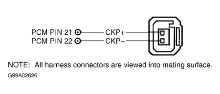
Ensure ignition is off. Disconnect PCM. Reconnect tester to vehicle wiring harness. Measure resistance between CKP+ jack and PWR GND jack at DIS tester. Also measure resistance between CKP+ jack and VPWR jack at DIS tester. If both resistance readings are more than 10,000 ohms, replace PCM and retest. If any resistance reading is 10,000 ohms or less, repair fault in CKP+ circuit.
245) Circuit Check
Measure resistance between CKP- jack and PWR GND jack at DIS tester. Also measure resistance between CKP- jack and VPWR jack at DIS tester. If any resistance reading is 10,000 ohms or less, go to next step. If both resistance readings are more than 10,000 ohms, replace CKP sensor and retest.
246) Isolate Short Circuit
Ensure ignition is off. Disconnect PCM. Reconnect DIS tester to vehicle wiring harness. Measure resistance between CKP- jack and PWR GND jack at DIS tester. Also measure resistance between CKP- jack and VPWR jack at DIS tester. If both resistance readings are more than 10,000 ohms, replace PCM and retest. If any resistance reading is 10,000 ohms or less, repair fault in CKP- circuit.
247) Check CKP Signal
Press DIS tester RESET button and wait 5 seconds for initialization. Crank or start engine. If CKP SIGNAL SYSTEM STATUS LED is off with engine running or during engine cranking, go to next step. If CKP SIGNAL SYSTEM STATUS LED is on, go to step 252).
248) Circuit Check
Turn ignition off. Disconnect CKP sensor. Measure resistance between CKP+ terminal at CKP sensor wiring harness connector and CKP+ jack at DIS tester. Also measure resistance between CKP- terminal at CKP sensor wiring harness connector and CKP- jack at DIS tester. If both resistance readings are less than 5 ohms, go to next step. If any resistance reading is 5 ohms or more, repair CKP circuit and retest.
249) Check For CKP+ Short
Leave ignition off. Measure resistance between CKP+ jack and jacks for CKP-, PWR GND and VPWR at DIS tester. If any resistance reading is 10,000 ohms or less, go to next step. If all resistance readings are more than 10,000 ohms, go to step 251).
250) Isolate Short Circuit
Ensure ignition is off. Disconnect PCM. Reconnect DIS tester to vehicle wiring harness. Measure resistance between CKP+ jack and jacks for CKP-, PWR GND and VPWR at DIS tester. If any resistance reading is 10,000 ohms or less, repair CKP+ circuit and retest. If all resistance readings are more than 10,000 ohms, replace PCM and retest.
251) CKP Sensor Check
Turn ignition off. Inspect CKP sensor and pulse wheel for damage and correct alignment. Service CKP sensor and pulse wheel as necessary. If no problems are found, replace CKP sensor and retest.
252) Wiggle Test Mode B: CKP Circuit
Turn ignition on. Set DIS tester WIGGLE TEST switch on. Set MODE switch to "B" position. Press DIS tester RESET button and wait 5 seconds for initialization. Wiggle and bend wiring harness and connectors. If FAULT MEMORY LEDs are off, go to next step. If any FAULT MEMORY LED is on, press RESET button and wait for initialization. Continue to test until intermittent fault is located. Repair as necessary and retest.
253) Check CKP SHD For Short To Power
Turn ignition off. Measure resistance between CASE GND/CKP SHD jack and VPWR jack at DIS tester. If resistance is 10,000 ohms or less, go to next step. If resistance is more than 10,000 ohms, go to step 255).
254) Isolate Short
Ensure ignition is off. Disconnect PCM. Reconnect DIS tester to vehicle wiring harness. Measure resistance between CASE GND/CKP SHD jack and VPWR jack at DIS tester. If resistance is 10,000 ohms or less, repair CASE GND/CKP SHD circuit and retest. If resistance is more than 10,000 ohms, replace PCM and retest.
255) Wiggle Test Mode B: CKP Circuit
Turn ignition on. Set DIS tester WIGGLE TEST switch on. Set MODE switch to "B" position. Press DIS tester RESET button and wait 5 seconds for initialization. Wiggle and bend wiring harness and connectors. If FAULT MEMORY LEDs are off, repair CASE GND/CKP SHD circuit and retest. If any FAULT MEMORY LED is on, press RESET button and wait for initialization. Continue to test until intermittent fault is located. Repair as necessary and retest.
SPONSORED LINKS
Wednesday, December 17th, 2008 AT 3:02 PM