Dash gauges going crazy

Tiny
TFASNACHT
  • MEMBER
  • 1999 FORD WINDSTAR
Six cylinder front wheel drive automatic 142,000 miles.

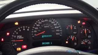
The dash gauges (speedometer, tachometer, temperature and gas) in my van have suddenly started going crazy crazy. I have owned it for two years and it had happened once or twice in that time. They would all "top out" and then quickly return to normal. I did not give it much thought after that. Recently they have started doing it constantly but now they will "stick" in different positions (i.E. 0, 40 or 120+ mph gas full, empty or half etc.) And they continue to bounce around. Usually the tachometer and speedometer together and the temperature and fuel together, sometimes all four. Can you please give me some indication where to start or am I looking at a more serious problem that I should not be doing myself?
Thursday, July 9th, 2009 AT 9:20 AM

6 Replies

Tiny
MERLIN2021
  • MECHANIC
  • 17,250 POSTS
It sounds like there is bad/loose solder joints inside the cluster. I would remove the cluster and replace it with a used or new one. Here is a video of the job being done with diagrams below to help you with your car.

https://youtu.be/_HEC44xENxw

Here is how it is done on your car.

Check out the diagrams (Below). Please let us know if you need anything else to get the problem fixed.

Cheers
Was this
answer
helpful?
Yes
No
+14
Thursday, July 9th, 2009 AT 9:49 AM
Tiny
TFASNACHT
  • MEMBER
  • 3 POSTS
Okay, I checked out the brake switch and there are no signs of a leak. The switch and the wiring under and around it are dry a can be. Any other ideas what could be causing my gauges to go crazy like this?
Was this
answer
helpful?
Yes
No
Sunday, July 12th, 2009 AT 10:07 AM
Tiny
MERLIN2021
  • MECHANIC
  • 17,250 POSTS
INSTRUMENT CLUSTER Instrument Cluster (IC) is a Hybrid Electronic Cluster (HEC). Vehicle electronic functions are divided into zones. Instrument cluster, Front Electronics Module (FEM) and Rear Electronics Module (REM) use Standard Corporate Protocol (SCP) communication network to transmit and receive information. IC communicates with FEM, REM, ABS/TC, PCM and other modules over SCP bus to control gauges and warning indicators. For standard or optional IC contents. See Fig. 1 or Fig. 2. Instrument cluster and panel lighting system provides dimmable backlighting to following components: instrument cluster, headlight switch, front climate control assembly, auxiliary climate control assembly (if equipped), audio unit, Rear Audio Control Panel (RACP), message center switch assembly (if equipped), front ashtray, overhead console, speed control actuator switches and traction control/reverse park aid override switch. Front power door lock switches and front power window switches are non-dimmable. RETRIEVING CODES (DEALER TEST MODE) Entering Dealer Test Mode 1. Depress and hold instrument cluster trip odometer/reset button. Turn ignition switch to ON position. Continue pressing trip odometer/reset button until "tESt" is displayed in odometer. 2. Trip odometer/reset button must be released within 3 seconds of odometer displaying "tESt" to begin dealer test mode. 3. If no codes were displayed using scan tool, depress trip odometer/reset button to advance through following modes until "dtc" is displayed. Depressing trip odometer/reset button will display any continuous DTC stored. If any DTC are stored, perform appropriate test in accordance with DTCs retrieved. See INSTRUMENT CLUSTER DTC INDEX table under RETRIEVING CODES (SCAN TOOL). 4. If no codes are stored, the following modes can be used to actuate instrument cluster displays. Depress trip odometer/reset button to advance through test modes. See DEALER TEST MODE DISPLAYS. Exiting Dealer Test Mode Turn ignition switch to OFF position, or press and hold trip odometer/reset button for 3 or more seconds, then release to exit instrument cluster dealer test mode. If no DTC are retrieved, repair by symptom. See SYMPTOM INDEX table under SYSTEM TESTS.
Was this
answer
helpful?
Yes
No
+8
Sunday, July 12th, 2009 AT 11:20 AM
Tiny
TFASNACHT
  • MEMBER
  • 3 POSTS
I performed the dealer test on the instrument cluster as described (this is spot on by the way) and I pulled five DTC codes from the instrument cluster. They do not correspond to the "normal" DTC codes (Pxxxx, Bxxxx, Cxxxx or Uxxxx) Can anyone help?
Here are the codes that I pulled from the dash:

dtc 9249
dtc 9676
dtc 9470
dtcd262
dtc 9246

Thanks,
Tyler
Was this
answer
helpful?
Yes
No
+2
Monday, July 20th, 2009 AT 10:27 AM
Tiny
MERLIN2021
  • MECHANIC
  • 17,250 POSTS
The only one I can find is 9676= Battery voltage out of range. Fix this first and retest, will probably correct the proble, "no communication with cluster"
TEST A: NO COMMUNICATION WITH INSTRUMENT CLUSTER 1. Turn ignition switch to OFF position. Disconnect instrument cluster 22-pin harness connector C239, and 20-pin harness connector C240. Turn ignition switch to ON position. Measure voltage between specified instrument cluster harness connector terminals and ground. See INSTRUMENT CLUSTER VOLTAGE table. If all readings are 10 volts or more, go to next step. If any reading is less than 10 volts, repair circuit.
CAUTION: Electronic modules are sensitive to static electrical charges. Proper grounding of technician and component is essential to prevent damage.


https://www.2carpros.com/forum/automotive_pictures/62217_9676_1.jpg


2. Turn ignition switch to OFF position. Measure resistance between instrument cluster harness connector C240 terminal No. 12 (Black wire) and ground. If resistance is less than 5 ohms, repair module communication concern. See MODULE COMMUNICATIONS NETWORK - WINDSTAR article. If resistance is 5 ohms or more, repair open or poor connection in Black wire to ground connector G304, located behind left kick panel.


https://www.2carpros.com/forum/automotive_pictures/62217_9676a_1.jpg

Was this
answer
helpful?
Yes
No
+1
Monday, July 20th, 2009 AT 12:49 PM
Tiny
BODEGUERO
  • MEMBER
  • 2 POSTS
Had a similar problem " needles crazy " I did my recommended without results until service panel (cluster) and anchor their points of defective welding corrected them (re-soldered) and goodbye problem. You must use a (lupa) lens increase which very good to view these welding points normal as the lens is not enough I hope you operate.
Was this
answer
helpful?
Yes
No
+5
Thursday, February 27th, 2014 AT 9:34 AM

Please login or register to post a reply.

Sponsored links