Hello -
Thanks for the information.
Well I am not sure what they mean by not being touched but it appears as you do need to disconnect the evaporator lines to get the HVAC out. All of the ones I have done I have had to do this too.
HEATER CORE
Removal & Installation
1. Disconnect negative battery cable. Remove instrument panel. See INSTRUMENT PANEL. Remove A/C evaporator housing assembly. See A/C EVAPORATOR HOUSING ASSEMBLY.
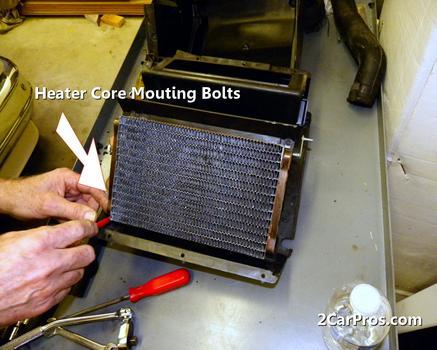
2. Remove heater core access cover from A/C evaporator cover housing. Remove tube gasket from heater core tubes. Slide heater core and seals from housing. To install, reverse removal procedure.
INSTRUMENT PANEL
Removal
1. Disconnect negative battery cable. Disable air bag system. See the AIR BAG RESTRAINT SYSTEM article in the ACCESSORIES/SAFETY EQUIPMENT section. Disconnect underhood wiring at left side of firewall. Working inside vehicle, disengage wiring connector from left kick panel. Carefully pull wiring harness into passenger compartment. Remove both kick panels. Remove radio antenna stanchion bolts. Disconnect radio antenna cable from base of antenna.
2. Remove steering column lower trim cover by removing 3 screws at bottom. Pull trim panel to disengage 3 snap-in retainers across top. Remove 4 screws attaching steering column lower opening reinforcement panel. Remove steering column upper and lower shrouds.
3. Disconnect A/C evaporator register duct from under steering column tube. Disconnect wiring from steering column. Remove shift interlock switch. Disconnect steering column pinch bolt. Support steering column, and remove 4 nuts retaining column to support. Remove steering column from vehicle.
4. Remove screw retaining left side of instrument panel to parking brake bracket. Disconnect pedal assembly wiring. Pull carpet back on both sides of dash and disconnect all wiring connectors with wiring leading into instrument panel.
5. Install steering column lower opening reinforcement using 4 screws (one on each corner). This procedure prevents instrument panel from twisting during removal from vehicle. Remove console assembly from vehicle. Remove 2 screws retaining console glove compartment to floor tunnel. Remove 2 screws retaining front of console to instrument panel. Remove console assembly.
6. Open glove box, squeeze sides of bin and lower box to full open position. Remove glove box assembly. From underneath instrument panel and through glove box opening, disconnect wiring and A/C-heater vacuum lines and control cables. Remove nut at right retaining instrument panel to cowl side. Remove 2 nuts at left retaining instrument panel to cowl side. Remove 2 nuts and one bolt to console bracket.
7. Remove right and left upper finish panels by pulling up to disengage snap-in retainers. Remove 6 bolts retaining instrument panel to cowl top. Remove right and left door rail trim panel. Remove door frame weatherstrip.
8. Carefully pull instrument panel away from cowl, and disconnect any remaining wiring or controls. Remove instrument panel from vehicle.
Installation
To install, reverse removal procedure. Steering column opening lower reinforcement must be installed on replacement panel before installing in vehicle.
A/C EVAPORATOR HOUSING ASSEMBLY
NOTE: If an A/C evaporator leak is suspected, evaporator core must be leak tested BEFORE removal. See LEAK TESTING in the A/C SYSTEM GENERAL SERVICING article in the A/C SYSTEM GENERAL SERVICING section.
Removal
1. Disconnect negative battery cable. Remove instrument panel. See INSTRUMENT PANEL.
2. Discharge A/C system using approved refrigerant recovery/recycling equipment. Remove high and low pressure hoses. Disconnect liquid line and suction accumulator-drier at evaporator. See REFRIGERANT LINES. Plug all openings to prevent contamination. Remove suction accumulator-drier. See ACCUMULATOR-DRIER.
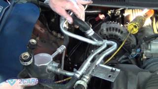
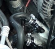
3. Remove throttle cable bracket and position aside (if necessary). Disconnect heater hoses from heater core tubes, and plug hoses and heater core tubes. Disconnect vacuum supply hose from the in-line A/C vacuum check valve.
4. Remove 3 evaporator assembly bolts from engine compartment side of firewall. In passenger compartment, remove screw attaching evaporator assembly support bracket to the top cowl panel. Remove one nut securing the bracket below A/C evaporator housing assembly to dash panel. Remove one nut retaining mount bracket at left end of evaporator housing to dash panel. Carefully pull assembly from dash panel and remove from vehicle.
Installation
To install, reverse removal procedure. Use NEW "O" rings lubricated with refrigerant oil. Evacuate, recharge and leak test system. See EVACUATING A/C SYSTEM, CHARGING A/C SYSTEM and LEAK TESTING in the A/C SYSTEM GENERAL SERVICING article in the A/C SYSTEM GENERAL SERVICING section.
REFRIGERANT LINES
Removal & Installation
1. Discharge A/C system using approved refrigerant recovery/recycling equipment. To remove refrigerant lines, fit appropriate spring lock coupling clamp on line. See SPRING LOCK COUPLING CLAMP table. See Fig. 8 .
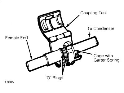
2. Close clamp, and push it into opening side of cage to expand garter spring and release female fitting. After garter spring is expanded, pull coupling apart.
3. To install, lubricate fittings with clean refrigerant oil and install NEW "O" rings. Push couplings together using a slight twisting motion. Ensure garter spring is over flared end of female fitting.
SPRING LOCK COUPLING CLAMP
Refrigerant Line Diameter Part Number
3/8" T81P-19623-G1
1/2" T81P-19623-G2
5/8" T831P-19623-C
3/4" T85L-19623-A
ACCUMULATOR-DRIER
Removal
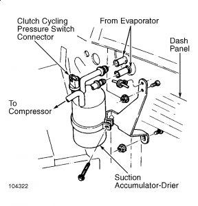
1. Discharge A/C system using approved refrigerant recovery/recycling equipment. On 3.8L EFI base engine, disconnect suction hose at compressor. Cap suction hose and compressor to prevent entry of dirt and moisture. On all other models, disconnect suction hose at suction accumulator-drier.
2. On all models, disconnect accumulator-drier inlet tube from evaporator core outlet. Disconnect wire harness connector from clutch cycling pressure switch located on top of accumulator-drier. Remove screw holding suction accumulator-drier to accumulator bracket, and remove suction accumulator-drier. See Fig. 7 .
Installation
To install, reverse removal procedure. Use new "O" rings lubricated with clean refrigerant oil. Evacuate, recharge and leak test system.
Okay, my thought. . .. . ..if it were me and I had it all tore apart I would be replacing my AC evaporator also. You have it apart, it's there. You will need to replace your dyer also depending on how long you have the system with no vacuum on it or without 134a. Then of course all of the O rings and orifice tube.
That is just me.
Definitely the O rings if not the other things.
Hope this helps.
Not sure where you are getting your parts but also check
http://www.rockauto.com/
and see what you think.
Sunday, January 3rd, 2010 AT 6:54 PM