Alternator Not Charging

Tiny
SATURNTECH9
  • MECHANIC
  • 30,870 POSTS
That sound's promising I would think that if it was a ground issue that the starter wouldn't work. Can you post a picture of the battery cable set up?Also now that you have cleaned the cable at idle what is the battery voltage at the battery. Also try this take off the positive cable and set your ohm's meter to low scale and check the ohm's value from the alternator case to the negative battery cable.
Was this
answer
helpful?
Yes
No
+1
Tuesday, November 2nd, 2010 AT 1:23 PM
Tiny
SATCHBOOGIE2U
  • MEMBER
  • 2 POSTS
Hello, if you had vehicle running and took ground ( - ) off while running Alternator is problem. The alternator should have supplied voltage for vehicle to continue to run, so what is happening vehicle runs on battery only. There was a time you could fix alternators yourself rebuilding them and getting the parts to do so was easy, but most likely the voltage regulator on the back of your particular alternator. You may want to see if you can find a regulator for your alternator, which would save you $ if you have a little know how on vehicles ! If alternator was charging volt meter should have read no less than 12.8 volts on old, new 13.5. So take care, this test works on most vehicles! A quick check you can take a wrench and with out hitting any positive wires touch the BACK of alternator in the dead center where bearing is, if alt is charging will attract wrench like a magnet on fords & gm vehicles. Have a blessed day !
Was this
answer
helpful?
Yes
No
+1
Wednesday, June 12th, 2019 AT 10:40 AM
Tiny
RONALD OLSTHOORN
  • MEMBER
  • 6 POSTS
  • 2003 FORD RANGER
  • 4.0L
  • 6 CYL
  • 4WD
  • AUTOMATIC
  • 120,000 MILES
Replaced alternator, checked all fusible links and still does not charge?
Was this
answer
helpful?
Yes
No
+1
Thursday, December 10th, 2020 AT 8:21 AM (Merged)
Tiny
CARADIODOC
  • MECHANIC
  • 33,729 POSTS
What is the symptom or test results that tell you it is not working?

Check for full battery voltage on the fat black/orange output wire and the smaller yellow/white wire. That should be on both when the engine is off.

With the ignition switch turned on, does the "battery" light on the dash turn on? If it does not, there is a break in the green/red wire or there is a blown 7.5 amp fuse. That is the turn-on signal for the voltage regulator. At the generator, you should find close to 2.0 volts on that wire when the ignition switch is on and the engine is not running. Once the engine is running, if the regulator sees output from the generator, it will put twelve volts on that green/red wire to turn the dash light off. Rather than wasting time trying to measure that, if the warning light was on, and it turns off once the engine is running, the regulator thinks the generator is working. Further proof would be to measure the white wire on the generator. That should have close to half of battery voltage, or 7.0 volts when the system is working.

If you find zero volts on the black/orange wire with the engine not running, and too-high voltage when it is running, there is a break in that wire going back to the battery. Check if there is a really large fuse bolted into the under-hood fuse box. If that is blown, it was due to the old generator or that terminal got shorted to ground, typically by bumping a wrench against it. If the fuse is not blown, check the bolts to be sure they are clean and tight. When the charging system is working properly, you must find between 13.75 and 14.75 volts at the generator's output terminal and across the battery's terminals.
Was this
answer
helpful?
Yes
No
+2
Thursday, December 10th, 2020 AT 8:21 AM (Merged)
Tiny
RONALD OLSTHOORN
  • MEMBER
  • 6 POSTS
Thanks for the diagnosis. My reply in caps after your questions.
What is the symptom or test results that tell you it is not working?

Check for full battery voltage on the fat black/orange output wire and the smaller yellow/white wire. That should be on both when the engine is off. Yes it is

with the ignition switch turned on, does the "battery" light on the dash turn on? Yes if it doesn't, there's a break in the green / red wire or there's a blown 7.5 amp fuse. That's the turn-on signal for the voltage regulator. At the generator, you should find close to 2.0 volts on that wire when the ignition switch is on and the engine is not running. I get one and a half volts. Once the engine is running, if the regulator sees output from the generator, it will put 12 volts on that green / red wire to turn the dash light off. When running same voltage. Rather than wasting time trying to measure that, if the warning light was on, and it turns off once the engine is running, the regulator thinks the generator is working. Further proof would be to measure the white wire on the generator. That should have close to half of battery voltage, or 7.0 volts when the system is working. Zero with igniton on and not running or when running.

If you find 0 volts on the black / orange wire with the engine not running, and too-high voltage when it's running, there's a break in that wire going back to the battery. All seems ok. Check if there is a really large fuse bolted into the under-hood fuse box. If that is blown, it was due to the old generator or that terminal got shorted to ground, typically by bumping a wrench against it. If the fuse is not blown, check the bolts to be sure they're clean and tight. When the charging system is working properly, you must find between 13.75 and 14.75 volts at the generator's output terminal and across the battery's terminals.
Fyi I have trued two new alternators thus far. Got me stumped.
Was this
answer
helpful?
Yes
No
Thursday, December 10th, 2020 AT 8:21 AM (Merged)
Tiny
CARADIODOC
  • MECHANIC
  • 33,729 POSTS
What is the voltage on the output wire when the engine is running?

Starting in the early 2000's, the engineers put an extra cover on the rear of their generators because they found them to be too easy to diagnose. If yours does not have that yet, look for the two test points on the back and measure those voltages. The right one with my nifty red arrow might have a gray plastic cap on it. That can be popped off or there will be a tiny hole in the center where you can fit the end of a straightened paper clip to take the reading. You should find twelve volts there all the time.

Before you move on to the next test, look at the black arrow in this photo and the silver button it is pointing to. Check if that is on your generator, or a wooden tooth pick, or piece of wire. I picked this photo because it shows the "nail" that holds the brushes retracted while the voltage regulator/brush assembly is being installed by the re-builder. They were supposed to remove that before testing the generator. If you see anything in that tiny hole, pull it out. You will hear two light clicks as the brushes extend to make contact.

Once that is removed, or if you do not find anything in that hole, you can move on to the next test. Check for voltage on the left test point, (blue arrow). If you find exactly the same as at the red arrow, the voltage regulator is defective. You can verify that by grounding the blue terminal. That will make the generator charge wide open, so do not raise engine speed. You will see battery voltage rise and/or the head lights will become brighter. You will hear the generator strain under the load too. Just ground that terminal long enough to get the results.

If you find zero volts at the blue test point, there is a break between the brushes. That is a typical failure at high mileage when the brushes are worn excessively, but not with a newly-rebuilt generator. I would be looking for a brush that got broken when an inexperienced person put it together and forgot to use the tooth pick to hold the brushes retracted until they were installed.

Under normal operation with the engine running, you can expect to find between roughly four and eleven volts on the blue terminal. The lower the voltage regulator pulls that down, the bigger is the difference between the two test points, the stronger is the magnetic field, and the more output current will be developed.

Tell me the voltages you find.
Was this
answer
helpful?
Yes
No
+2
Thursday, December 10th, 2020 AT 8:21 AM (Merged)
Tiny
RONALD OLSTHOORN
  • MEMBER
  • 6 POSTS
Is there any chance the battery could be defective? I boosted the car and removed the battery cable and the engine stalled which leads me to believe it is not charging.
I cannot see the back of the alternator now that it is installed but wanted to rule the battery out first before in remove the alternator to check on your latest suggestions ( I am doubtful as this is the second new alternator).
Was this
answer
helpful?
Yes
No
+1
Thursday, December 10th, 2020 AT 8:21 AM (Merged)
Tiny
CARADIODOC
  • MECHANIC
  • 33,729 POSTS
Please do not disconnect the battery when the engine is running

Every year I did a demonstration on the generator test bench for my students to show what can happen when you do that. It was real easy for the voltage to reach over 35 volts. That will destroy any computer on the vehicle, the generator's internal diodes and built-in voltage regulator, and any light bulbs that are turned on.

The thinking is that if you disconnect either cable and the engine stays running, the generator must be working but a lot of them will stop working due to the voltage regulator responding to the dips in the "ripple" voltage being produced. That will make a perfectly good generator appear to be bad so that test is not valid.

If a mechanic is caught pulling this stunt he will typically get one verbal warning. For the second offense he will be fired. It is that big a deal.

Some generators respond to the high points in the ripple. That momentary higher voltage goes right back to the field winding and creates a stronger magnetic field. That stronger electromagnet creates a higher output voltage which again creates a stronger electromagnet. It is a vicious circle and voltage can keep on rising until something gives out. The main thing that smooths out that ripple so it does not affect the voltage regulator or the generator is the battery.

Three things are needed to generate the output current. They are a magnet, (electromagnet, in this case), a coil of wire, and most importantly, movement between them. That is why the belt needs to make it spin. One thing that can save you from doing damage by removing a battery cable is not raising engine speed. Generators are relatively inefficient at low engine speeds and their output voltage is less likely to rise to dangerous levels, ... As long as you do not raise engine speed.

One other thing to keep in mind is batteries give off explosive hydrogen gas. Regardless if your generator is working or not there is going to be a big spark when you remove a battery cable with the engine running. Either the generator's current will be recharging the battery, and that can be up to 20 amps, or the battery is going to be supplying the car's electrical systems, and that can easily be over 30 amps. That kind of current is going to create a big spark when a connection is broken or reconnected. Small arc welders run as low as 40 to 60 amps and look at the sparks they create. The reason we do not hear about more battery explosions is because people are careful to not disconnect the cables when there is current flowing through them. It is also why there are huge warning labels on all battery chargers to be sure they are turned off before connecting or disconnecting them from the battery.

Another common generator problem is one defective diode out of the six. You will lose exactly two thirds of the generator's capacity but system voltage will remain normal or it could even be just a little high from the voltage regulator responding to the greatly increased dips in the ripple voltage.

It is always a good idea to wear safety glasses when working around car batteries, but if you still insist on removing a cable while the engine is running, a face shield makes more sense, and have plenty of water on hand to wash any acid off the vehicle's paint.

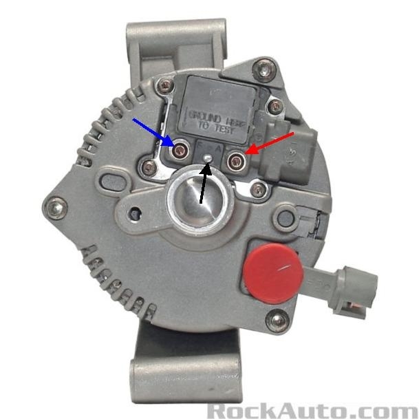
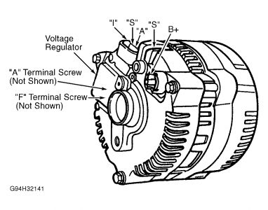
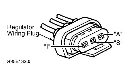
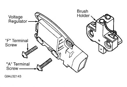
Ford used to have a really nice generator design that allowed testing right on the back of the unit. Only Chrysler alternators are easier to diagnose. Unfortunately the engineers do not really care about ease of service on GM's and many other brands.

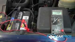
The way you tell if the charging system is working is to measure the battery voltage while the engine is running. It must be between 13.75 and 14.75 volts. There still could be a bad diode though. You need a professional load tester to test for that. Ripple will be very high and the most output current you will get will be one third of the generator's design value. That is not enough to meet the demands of the electrical system under all conditions so the battery will have to make up the difference, until it runs down.
Was this
answer
helpful?
Yes
No
+1
Thursday, December 10th, 2020 AT 8:21 AM (Merged)
Tiny
BOUSSE
  • MEMBER
  • 3 POSTS
  • 2003 FORD RANGER
  • 150 MILES
This truck has a 3.0.

Brand new alternator brand new battery. Both tested and okay.
Battery light comes on in the dash.
Volts read twelve when running, 12.3 when off.

I have done some reading on the forums but still cannot find a solution.

Any ideas?
Was this
answer
helpful?
Yes
No
Thursday, December 10th, 2020 AT 8:21 AM (Merged)
Tiny
HMAC300
  • MECHANIC
  • 48,601 POSTS
Check fuse and fusible links one may be burnt out that is not supplying power to activate it. See picture these are available at auto parts and must be the same gauge.
Was this
answer
helpful?
Yes
No
Thursday, December 10th, 2020 AT 8:21 AM (Merged)
Tiny
CARADIODOC
  • MECHANIC
  • 33,729 POSTS
I would try to use a small mirror to look at the back of the generator to see if that tooth pick is still in there. Next, since you cannot get to the test terminals, consider unbolting the generator so we can do some continuity tests on the work bench.

Measure between the "ground here to test" terminal, (blue arrow in my sad photo), and the twelve volt feed terminal, (red arrow). You should find very close to 4 ohms, but be aware the brushes commonly do not make a good connection when the rotor is not spinning. You may have to turn the pulley a little to get a reading.

As long as the plug is disconnected, recheck the voltage on the large black/orange wire and the yellow/white wire, but use a test light instead of a digital voltmeter. Both of these circuits are protected by fuse link wires which are just normal wires but of a small gauge. If one of those burns open, it will leave a carbon track behind where it arced inside the insulation. That carbon is more than enough to let a tiny tickle of current through that a voltmeter can see the twelve volts, but there is no way you are going to get enough current through there to run the voltage regulator. There is also no way you will get enough current through there to run a test light. That is why the test light is more accurate for this type of test.
Was this
answer
helpful?
Yes
No
Thursday, December 10th, 2020 AT 8:21 AM (Merged)
Tiny
BOUSSE
  • MEMBER
  • 3 POSTS
Any idea which fuse it is in the engine compartment? The fuse in the cab seems to just run the battery voltage meter. It is good.
I am checking the fuse links now.
Was this
answer
helpful?
Yes
No
Thursday, December 10th, 2020 AT 8:21 AM (Merged)
Tiny
RONALD OLSTHOORN
  • MEMBER
  • 6 POSTS
I would try to use a small mirror to look at the back of the generator to see if that tooth pick is still in there. Not there. Next, since you cannot get to the test terminals, consider unbolting the generator so we can do some continuity tests on the work bench.

Measure between the "ground here to test" terminal, (blue arrow in my sad photo), and the twelve volt feed terminal, (red arrow). You should find very close to 4 ohms, I get 2.8 OHMS. But be aware the brushes commonly do not make a good connection when the rotor is not spinning. You may have to turn the pulley a little to get a reading.

As long as the plug is disconnected, recheck the voltage on the large black/orange wire and the yellow/white wire, yellow wire will no illuminate the test light. Must be a fusible link. Have to find it? But use a test light instead of a digital voltmeter. Both of these circuits are protected by fuse link wires which are just normal wires but of a small gauge. If one of those burns open, it will leave a carbon track behind where it arced inside the insulation. That carbon is more than enough to let a tiny tickle of current through that a voltmeter can see the twelve volts, but there is no way you are going to get enough current through there to run the voltage regulator. There is also no way you will get enough current through there to run a test light. That is why the test light is more accurate for this type of test.
Was this
answer
helpful?
Yes
No
Thursday, December 10th, 2020 AT 8:21 AM (Merged)
Tiny
BOUSSE
  • MEMBER
  • 3 POSTS
Just green dust left in the end of the fuse links. Lol.
Thanks for the help man, I hate wiring and you saved me on this one.
How do I go about replacing these without going to a Ford dealership?
Was this
answer
helpful?
Yes
No
Thursday, December 10th, 2020 AT 8:21 AM (Merged)
Tiny
RONALD OLSTHOORN
  • MEMBER
  • 6 POSTS
I stand corrected. Both the black/orange and the yellow white, at the alternator, illuminate the test light?
Any other ideas?
Was this
answer
helpful?
Yes
No
Thursday, December 10th, 2020 AT 8:21 AM (Merged)
Tiny
HMAC300
  • MECHANIC
  • 48,601 POSTS
You look at the diagram I sent and see what gauge it is then go to auto parts and buy one of comparable length and splice it in preferably by soldering it then shrink tube where you spliced it to protect it.
Was this
answer
helpful?
Yes
No
+1
Thursday, December 10th, 2020 AT 8:21 AM (Merged)
Tiny
CARADIODOC
  • MECHANIC
  • 33,729 POSTS
Next is to ground the "ground here to test" terminal while the engine is running. That bypasses the voltage regulator and makes the generator charge wide open. Do not raise engine speed because if the generator is working, system voltage can rise too high and do a lot of damage. I turn on the head lights so I can watch their brightness change, but you can do the same thing by watching a voltmeter or test light connected to the battery terminals. All generators are very inefficient at low speeds, but you still want to do this test just long enough to get the results, then you are done. This should only take a couple of seconds.

If the lights get brighter when you ground that terminal, the generator is working, (at least partially), and the voltage regulator is defective.

If there is no change when you ground that terminal, there is a bad connection on one or both brushes. There are other potential causes, but they are very uncommon. You will find worn or broken brushes 99.9 percent of the time.
Was this
answer
helpful?
Yes
No
Thursday, December 10th, 2020 AT 8:21 AM (Merged)
Tiny
RANDYRJOHNSON2002
  • MEMBER
  • 1 POST
  • 2003 FORD RANGER
  • 6 CYL
  • 2WD
  • AUTOMATIC
  • 75,000 MILES
I have an o3 ranger 4.0 that does not charge. The alternator checks out and I ran a test by grounding out the f terminal on the regulator jumpering the a term and read voltage acroos the a and s terminal connector and I had.5 on s and nothing on a
can you point me in the right direction to try next?
Was this
answer
helpful?
Yes
No
Thursday, December 10th, 2020 AT 8:21 AM (Merged)
Tiny
BMRFIXIT
  • MECHANIC
  • 19,053 POSTS
1.Measure voltage between ground and generator terminal B+ (Black/Orange wire)


https://www.2carpros.com/forum/automotive_pictures/99387_Graphic1_185.jpg


. If battery voltage is present, go to next step. If battery voltage is not present, repair open in Black/Orange wire between generator and battery junction box.
2.Disconnect generator 3-pin harness connector. Measure voltage between ground and generator harness connector terminal "A" (Yellow/White wire). If battery voltage is present, go to next step. If battery voltage is not present, repair circuit between battery and generator.

3.Turn ignition on. Measure voltage between ground and generator harness connector terminal "I" (Light Green/Red wire). If voltage is equal to battery voltage, go to next step. If voltage is not equal to battery voltage, repair open in Light Green/Red wire between generator connector and instrument cluster.

4.Connect generator 3-pin harness connector. Start engine and let idle. Measure voltage between positive battery terminal and generator terminal B+ (Black/Orange wire). If voltage drop is less than 0.5 volt, replace generator. If voltage drop is 0.5 volt or more, repair circuit between generator and battery.


https://www.2carpros.com/forum/automotive_pictures/99387_Graphic2_90.jpg


https://www.2carpros.com/forum/automotive_pictures/99387_Graphic3_43.jpg

Was this
answer
helpful?
Yes
No
+6
Thursday, December 10th, 2020 AT 8:21 AM (Merged)
Tiny
RONALD OLSTHOORN
  • MEMBER
  • 6 POSTS
I cannot see which terminal it is? The alternator is mounted again and your picture is not quite in focus enough?
Thanks.
Was this
answer
helpful?
Yes
No
Thursday, December 10th, 2020 AT 8:21 AM (Merged)

Please login or register to post a reply.

Sponsored links