The vehicle security systems I've ever installed required either a remote or a keypad to arm and disarm the system. The keys lock and unlock the doors, but the security system requires an electrical impulse of some sort to activate.
Ok, found some information that may be of assistance to you:
TESTING
Before performing any tests on anti-theft system, check the following items to eliminate common
problems:
� Hood/trunk/liftgate properly aligned.
� Door locks not binding.
� Fuses not blown.
� Loose or corroded connections.
� Damaged wiring harness.
� Damaged anti-theft control module.
Horn, headlights, hazard flashers, interior lights, trunk lights, power door locks and remote
keyless entry system operation.
�
LOCK SWITCH TESTING
Remove lock switch. Measure resistance between switch terminals. With switch in neutral position,
resistance should be 25 k/ohms or greater. With switch in unlock position, resistance should be less
than 200 ohms. Replace switch if resistance is not within specification.
FLASH CODE TEST
NOTE: Use this test to quickly identify a short to ground in the door lock
cylinder switches, hood switch, ignition lock anti-theft switch or their
associated circuits.
Turn ignition switch to ACCESSORY position check THEFT indicator lamp. If lamp lights
steadily for 10 seconds, check ignition lock anti-theft switch and circuit No. 936 (Dark
Green/White) wire. If lamp operates normally, go to next step.
1.
Activate power door unlock button 5 times within 10 seconds. Count number of flashes of the
anti-theft warning indicator lamp. If there is only one flash, system is normal, go to PINPOINT
TEST DIRECTORY TABLE. If there are 2 flashes displayed, go to next step. If there are 3
flashes displayed, go to step 4). If there are 4 flashes displayed, go to step 5).
2.
Two flashes indicate door lock cylinder switch input shorted. Repair or replace door lock
cylinder switches and circuit No. 25 (Dark Green/Purple wire).
3.
Three flashes indicate hood anti-theft switch and/or trunk lock cylinder switch input shorted.
Repair or replace hood anti-theft switch and/or trunk lock cylinder switch and circuit No. 23
(Tan/Light Green wire).
4.
Four flashes indicate door lock cylinder switch, hood anti-theft switch and/or trunk lock
cylinder switch input shorted. Repair or replace door lock cylinder switch, hood anti-theft
switch and/or trunk lock cylinder switch and related circuits.
5.
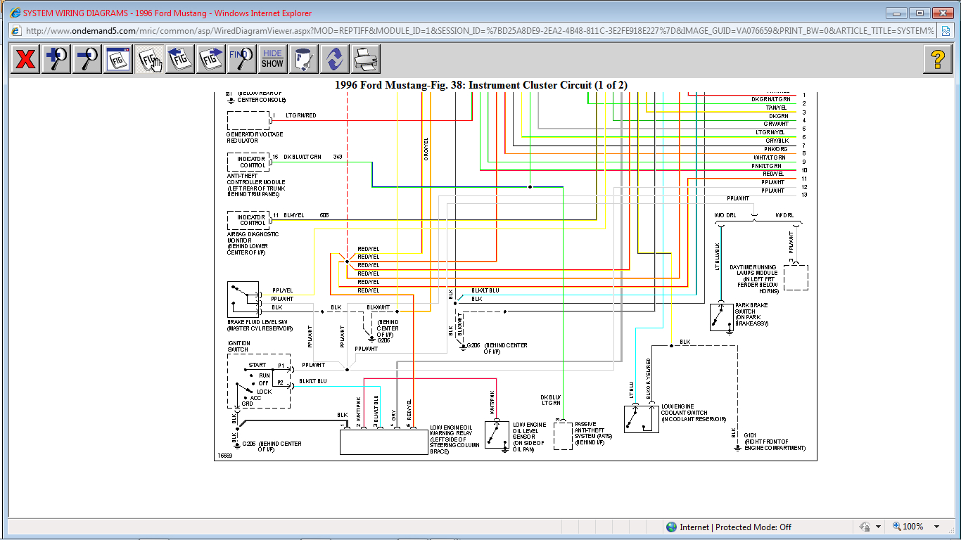
Fig. 1: Anti-Theft Control Module Connector Pin ID (Mustang)
Courtesy of FORD MOTOR CO.
ANTI-THEFT SYSTEM -1996 Ford Mustang Page 1 of 7
PINPOINT TEST DIRECTORY
Use the following directory to determine individual pinpoint tests for anti-theft system.
PINPOINT TEST DIRECTORY
Symptom Pinpoint Test
Alarm Does Not Arm Properly A
Alarm Does Not Disarm Properly B
Alarm Does Not Activate Properly C
Starter Will Not Crank D
Alarm Indicator Light Always On E
Alarm Indicator Light Does Not Work F
Horn & Headlights Are Always On G
System Triggers False Alarms H
PINPOINT TEST A - ALARM DOES NOT ARM PROPERLY
Start vehicle, then turn ignition off. Disconnect Anti-Theft Control Module connectors. With
doors closed, measure voltage at Anti-Theft Control Module connector C2, terminal No. 14.
See Fig. 1. If voltage is less than 9 volts, go to step 3). If voltage is more than 9 volts, go to
next step.
1.
Disconnect both courtesy lamp switches. Measure voltage at Anti-Theft Control Module
connector C2, terminal No. 14. If voltage is less than 9 volts, check door courtesy switches and
retest system. If voltage is more than 9 volts, repair short to battery power in circuit No. 24
(Dark Blue/Orange wire) and retest system.
2.
Disconnect Anti-Theft Control Module connectors. Measure resistance between connector C1,
terminal No. 6 (Dark Green/Purple wire) and connector C2, terminal No. 26 (Black/White
wire). If resistance is less than 100 ohms, go to next step. If resistance is more than 100 ohms,
go to step 6).
3.
Disconnect driver and passenger door lock cylinder switches. Measure resistance between
connector C1, terminal No. 6 (Dark Green/Purple wire) and connector C2, terminal No. 26
(Black/White wire). If resistance is less than 100 ohms, repair short to ground in circuit No. 25
(Dark Green/Purple wire) and retest system. If resistance is more than 100 ohms, go to next
step.
4.
Measure resistance across driver door lock cylinder switch terminals, repeat for passenger side.
If resistance is less than 100 ohms, replace door lock cylinder switch and retest. If resistance is
more than 100 ohms, go to next step.
5.
Disconnect Anti-Theft Control Module connectors and Remote Keyless Entry Module
connector. Turn ignition off. Measure voltage to ground (terminal No. 26, Black/White wire)
between Anti-Theft Control Module connector C2, terminal No. 8 (Red/Orange wire),
connector C1, terminal No. 7 (Pink/Orange wire), connector C2, terminal No. 9 (Pink/Black
wire) connector C1, terminal No. 4 (White/Purple wire). If any or all voltages are more than 2
volts, repair short to battery power in circuit No. 117 (Pink/Black wire), No. 118 (Pink/Orange
wire), No. 163 (Red/Orange wire) and/or No. 296 (White/Purple wire) and retest system. If all
voltages are less than 2 volts, go to next step.
6.
ANTI-THEFT SYSTEM -1996 Ford Mustang Page 2 of 7
Turn Ignition off. Connect jumper wires between Remote Keyless Entry Module connector C3
terminal No. 16, No. 3, No. 6 and ground. See KEYLESS ENTRY SYSTEM - REMOTE
article. Measure resistance between Anti-Theft Control Module connector C2, terminal No. 9
(Pink/Black wire) and terminal No. 26 (Green Yellow/Red wire). Repeat procedure between
Anti-Theft Control Module connector C1, terminal No. 7 (Pink/Orange wire) and connector C2.
Terminal No. 8 (Red/Orange wire). If resistance is more than 100 ohms on any terminal, repair
open on circuit No. 117 (Pink/Black wire), No. 118 (Pink/Orange wire) and/or No. 163
(Red/Orange wire) and retest system. If all readings are more than 100 ohms, go to next step.
7.
Measure resistance to ground (terminal No. 26, Green Yellow/Red wire) between Anti-Theft
Control Module connector C1, terminal No. 7 (Pink/Orange wire) connector C2, terminal No. 8
(Red/Orange wire) and connector C2. Terminal No. 9 (Pink/Black wire). If resistance is less
than 100 ohms, repair short to ground in circuit No. 117 (Pink/Black wire), No. 118
(Pink/Orange wire) and/or No. 163 (Red/Orange wire) and retest system. If all readings are
more than 100 ohms, go to next step.
8.
Measure voltage at Anti-Theft Control Module connector C1, terminal No. 7 (Pink/Orange
wire) and connector C2, terminal No. 26 (Green Yellow/Red wire). If voltage reading is more
than 9 volts, go to step 11). If reading is less than 9 volts, go to next step.
9.
Check 20-amp inline fuse (from fuse junction panel). If fuse is blown, replace fuse and retest
system. If fuse is good, repair open circuit No. 196 (Dark Blue/Orange wire) and test system.
10.
Reconnect Anti-Theft Control Module connectors and Remote Keyless Entry Module
connector. Ensure voltage at Anti-Theft Control Module connector C1, terminal No. 7
(Pink/Orange wire) is less than 2 volts and that a momentary battery voltage signal is present at
connector C2, terminal No. 9 (Pink/Black wire) when doors are locked via keyless entry lock
code (7/8 and 9/0) or remote transmitter LOCK button. If voltage reading is correct, replace
Anti-Theft Control Module and retest system. If voltage reading is not correct, go to next step.
11.
Disconnect Anti-Theft Control Module connectors. Ensure voltage at Anti-Theft Control
Module connector C1, terminal No. 7 (Pink/Orange wire) is less than 2 volts and that a
momentary battery voltage signal is present at connector C2, terminal No. 9 (Pink/Black wire)
when doors are locked via keyless entry lock code (7/8 and 9/0) or remote transmitter LOCK
button. If voltage reading is correct, replace Anti-Theft Alarm Control Module and retest
system. If voltage reading is not correct, check for malfunction in Keyless Entry System or
remote transmitter. See KEYLESS ENTRY SYSTEM - REMOTE article.
12.
PINPOINT TEST B - ALARM DOES NOT DISARM PROPERLY
Start vehicle, then turn ignition off. Disconnect Anti-Theft Control Module connectors and
Remote Keyless Entry Module connector. Connect a jumper wire between Remote Keyless
Entry Module connector C3, terminal No. 3 (Red/Yellow wire) and terminal No. 6 (Black
wire). See Fig. 1. Measure resistance between Anti-Theft Control Module connector C2,
terminal No. 8 (Red/Orange wire) and terminal No. 26 (Black/White wire). Repeat procedure
for Anti-Theft Control Module connector C1, terminal No. 7 (Pink/Orange wire) and terminal
No. 26 (Black/White wire). If resistance is less than 100 ohms for both readings, go to next
step. If resistance is more than 100 ohms for either readings, repair open in circuit No. 163
(Red/Orange wire) or circuit No. 118 (Pink/Orange wire) and retest system.
1.
Turn ignition on. Measure voltage between Anti-Theft Control Module connector C1, terminal
No. 7 and terminal No. 26 (Black/White wire). If voltage is more than 9 volts, go to next step. If
voltage is less than 9 volts, go to step 4)
2.
Check 10-amp fuse No. 5 from fuse junction panel. If fuse is bad, replace fuse and retest
system. If fuse is good, repair open in circuit No. 296 (White/Purple wire) and retest system.
3.
ANTI-THEFT SYSTEM -1996 Ford Mustang Page 3 of 7
Connect Remote Keyless Entry Module connector. Unlock door lock with key, leaving key
rotated to unlock position. Measure resistance between Anti-Theft Control Module connector
C1, terminal No. 6 (Dark Green/Purple wire) and terminal No. 26 (Black/White wire). Repeat
procedure for passenger door. If both readings are more than 100 ohms, go to next step. If both
readings are less than 100 ohms, go to step 6).
4.
Disconnect driver door lock cylinder switch. Check for continuity across door lock cylinder
switch terminals while turning lock cylinder with key. Repeat procedure for passenger door
lock cylinder switch. If there is continuity with key in unlock position and no continuity with
key in lock position, repair open in circuit No. 25 (Dark Green/Purple wire) and retest system.
If continuity is not as stated above, replace damaged door lock cylinder switch(es) and retest
system.
5.
Connect Anti-Theft Control Module connectors. Ensure voltage at Anti-Theft Control Module
connector C2, terminal No. 9 (Pink/Black wire) is less than 2 volts and that a momentary
battery voltage signal is present at connector C2, terminal No. 8 (Red/Orange wire) when doors
are unlocked via keyless entry unlock code or remote transmitter UNLOCK button. If voltage
reading is correct, replace Anti-Theft Control Module and retest system. If voltage reading is
incorrect, go to next step.
6.
Disconnect Anti-Theft Control Module connectors. Ensure voltage at Anti-Theft Control
Module connector C2, terminal No. 9 (Pink/Black wire) is less than 2 volts and that a
momentary battery voltage signal is present at connector C2, terminal No. 8 (Red/Orange wire)
when doors are unlocked via keyless entry unlock code or remote transmitter UNLOCK button.
If voltage reading is correct, replace Anti-Theft Control Module and retest system. If voltage
reading is incorrect, problem is in Remote Keyless Entry System. See appropriate KEYLESS
ENTRY SYSTEM - REMOTE article.
7.
PINPOINT TEST C - ALARM DOES NOT ACTIVATE PROPERLY
Start vehicle, then turn ignition off. Disconnect Anti-Theft Control Module connectors. Open
hood. Measure resistance between Anti-Theft Control Module connector C1, terminal No. 5
(Tan/Light Green wire) and connector C2, terminal No. 26 (Black/White wire). See Fig. 1. If
resistance is less than 100 ohms, go to step 3). If resistance is more than 100 ohms, got to next
step.
1.
Disconnect hood anti-theft switch. Measure resistance between hood anti-theft switch terminals
while depressing and releasing switch plunger. If resistance is more than 100 ohms when switch
is depressed and less than 100 ohms when switch is released, switch is okay. Repair open in
circuit No. 23 (Tan/Light Green wire). If resistance is not correct, replace hood anti-theft switch
and retest system.
2.
Connect Anti-Theft Control Module. Open driver door only. Measure voltage between Anti-
Theft Control Module connector C2, terminal No. 14 (Dark Blue/Orange) and connector C2,
terminal No. 26 (Black/White wire). Repeat procedure with passenger door. If voltage is more
than 9 volts, go to step 5). If voltage is less than 9 volts, go to next step.
3.
Disconnect driver door courtesy light switch. Connect a jumper wire between courtesy light
wiring harness terminals. Measure voltage between Anti-Theft Control Module connector C2,
terminal No. 14 (Dark Blue/Orange wire) and connector C2, terminal No. 26 (Black/White
wire). Repeat procedure with passenger door. If voltage is more than 9 volts, repair or replace
courtesy light switches and retest system. If voltage is less than 9 volts, repair open in circuit
No. 24 (Dark Blue/Orange wire) and retest system.
4.
ANTI-THEFT SYSTEM -1996 Ford Mustang Page 4 of 7
Arm alarm system with window down. Reach inside and open door using inside door handle. If
alarm triggers, system is okay. If alarm does not trigger, replace Anti-Theft Control Module and
retest system.
5.
PINPOINT TEST D - STARTER WILL NOT CRANK
NOTE: PINPOINT TEST D is only for conditions where the engine will not crank
at all. If models with 4.6L engines will crank for one second and then
stall, see ANTI-THEFT SYSTEM - PASSIVE article.
Arm, then disarm system. Attempt to start engine. If engine starts, system is okay. If engine will
not start, go to next step.
1.
Turn ignition off. Disconnect Anti-Theft Control Module connectors. Connect a jumper wire
between Anti-Theft Control Module connector C2, terminal No. 12 (White/Pink wire) and
connector C2, terminal No. 26 (Black/White wire). See Fig. 1. If engine does not start, go to
next step. If engine would not start in step 1) but starts now, replace Anti-Theft Control Module
and retest system.
2.
Remove jumper wire and measure voltage between Anti-Theft Control Module connector C2,
terminal No. 12 (White/Pink wire) and connector C2, terminal No. 26 (Black/White wire). If
voltage is more than 9 volts, go to next step. If voltage is less than 9 volts, repair open in circuit
No. 33 (White/Pink wire).
3.
Turn ignition off. Connect a jumper wire between Anti-Theft Control Module connector C2,
terminal No. 12 (White/Pink wire) and terminal No. 24 (Red/Light Blue wire). Measure voltage
across starter motor solenoid terminals while turning ignition to start. If voltage is more than 9
volts, repair or replace starter motor solenoid and retest system. If voltage is less than 9 volts,
repair open in circuit No. 32 (Red/Light Blue wire) and retest system.
4.
PINPOINT TEST E - ALARM INDICATOR LIGHT ALWAYS ON
NOTE: On models with 4.6L engines, Alarm Indicator Light is shared by Anti-
Theft Alarm System and Passive Anti-Theft System. The Anti-Theft
Alarm System uses the indicator light when ignition is off and the
Passive Anti-Theft uses the indicator light when ignition is in run or
start. See ANTI-THEFT SYSTEM - PASSIVE article.
Remove key from ignition. With doors closed and unlocked, observe alarm indicator light. If
light is not flashing continuously, go to next step. If light is flashing continuously, go to step 3).
1.
With key removed from ignition and doors closed and unlocked, observe alarm indicator light.
If light is on continuously, go to step 5). If light is not on continuously, system is okay.
2.
Disconnect Anti-Theft Control Module connectors. Close both doors. Measure voltage between
Anti-Theft Control Module connector C2, terminal No. 14 (Dark Blue/Orange wire) and
connector C2, terminal No. 26 (Black/White wire). See Fig. 1. If voltage is more than 9 volts,
go to next step. If voltage is less than 9 volts, replace Anti-Theft Control Module and retest
system.
3.
Disconnect driver door and passenger door courtesy light switches. Measure voltage between
Anti-Theft Control Module connector C2, terminal No. 14 (Dark Blue/Orange wire) and
connector C2, terminal No. 26 (Black/White wire). If voltage is more than 9 volts, repair short
4.
ANTI-THEFT SYSTEM -1996 Ford Mustang Page 5 of 7
to battery power in circuit No. 24 (Dark Blue/Orange wire) and retest system. If voltage is less
than 9 volts, repair or replace courtesy light switch(es) and retest system.
Disconnect Anti-Theft Control Module connectors. If alarm indicator light goes out, replace
Anti-Theft Control Module and retest system. If alarm indicator light does not go out, repair
short to ground in circuit No. 343 (Dark Blue/Light Green wire) and retest system.
5.
PINPOINT TEST F - ALARM INDICATOR LIGHT DOES NOT WORK
Start vehicle, then turn off. Disconnect Anti-Theft Control Module connectors. Connect a
jumper wire between Anti-Theft Control Module connector C1, terminal No. 15 (Dark
Blue/Light Green wire). See Fig. 1. If light turns on, replace Anti-Theft Control Module and
retest system. If light does not turn on, go to next step.
1.
Check 15-amp INT LPS fuse and anti-theft indicator bulb. If either are bad, replace and retest
system. If fuse and bulb are good, repair circuit No. 54 (Light Green/Yellow wire) and/or
circuit No. 343 (Dark Blue/Dark Green wire) and retest system.
2.
PINPOINT TEST G - HORN & HEADLIGHTS ARE ALWAYS ON
Disconnect anti-theft control module. If horn turns off, replace anti-theft control module and
retest system. If horn remains on, service horn circuit and retest system.
1.
Disconnect anti-theft control module. If low beam headlights turn off, replace anti-theft control
module and retest system. If low beam headlights remain on, repair short to battery power in
circuit No. 13 (Red/Black wire). If parklights remain on, repair short to battery power in circuit
No. 14 (Brown wire). Retest system.
2.
PINPOINT TEST H - SYSTEM TRIGGERS FALSE ALARMS
NOTE: Ensure that system triggers false alarms on a regular basis before
performing steps 2) through 5).
Disconnect anti-theft control module. Close doors and hood. Measure resistance between Anti-
Theft Control Module connector C1, terminal No. 5 (Tan/Light Green wire) and connector C2,
terminal No. 26 (Black/White wire). If resistance is more than 100 ohms, go to step 7). If
resistance is less than 100 ohms, go to next step.
1.
Open hood and trunk. Disconnect hood anti-theft switch and trunk anti-theft switch. Measure
resistance between Anti-Theft Control Module connector C1, terminal No. 5 (Tan/Light Green
wire) and connector C2, terminal No. 26 (Black/White wire). If resistance is more than 100
ohms, go to next step. If resistance is less than 100 ohms, repair short to ground in circuit No.
23 (Tan/Light Green wire) and retest system.
2.
Measure continuity between hood anti-theft switch terminals while depressing and releasing
switch plunger. If continuity is not present when switch is depressed and is present when switch
is released, go to next step. If continuity is not correct, replace hood anti-theft switch and retest
system.
3.
Reconnect hood switch and close hood. Measure resistance between Anti-Theft Control Module
connector C1, terminal No. 5 (Tan/Light Green wire) and connector C2, terminal No. 26
(Black/White wire). If reading is 100 ohms or more, go to next step. If reading is less than 100
ohms, adjust hood switch so that switch plunger is depressed when hood is closed. Retest
system.
4.
ANTI-THEFT SYSTEM -1996 Ford Mustang Page 6 of 7
Check trunk lock cylinder switch for short to ground or intermittent short to ground by
measuring continuity between trunk lock cylinder switch terminals. Jiggle switch wiring and
lock cylinder with keys. If continuity or intermittent continuity, indicating short to ground, is
not present, replace Anti-Theft Control Module and retest. If continuity or intermittent
continuity is present, replace trunk lock cylinder switch and retest system.
5.
Connect Anti-Theft Control Module connectors and close all doors. Measure voltage between
Anti-Theft Control Module connector C2, terminal No. 14 (Dark Blue/Orange) and terminal
No. 26 (Black/White wire). If voltage is less than 9 volts, go to step 8). If voltage is more than 9
volts, go to next step.
6.
Disconnect driver door and passenger door courtesy light switches. Measure voltage between
Anti-Theft Control Module connector C2, terminal No. 14 (Dark Blue/Orange) and connector
C2, terminal No. 26 (Black/White wire). If voltage is more than 9 volts, repair short to battery
power in circuit No. 24 (Dark Blue/Orange wire) and retest system. If voltage is less than 9
volts, repair or replace courtesy light switch(es) and retest system.
7.
Turn ignition off. Measure resistance between Anti-Theft Control Module connector C2,
terminal No. 10 (Dark Green/White wire) and terminal No. 26 (Black/White wire). If resistance
is 150-175 ohms, replace Anti-Theft Control Module only if steps 1) through 4) have been
performed. Retest system. If resistance is not 150-175 ohms, replace ignition lock cylinder
tamper switch and retest system.
8.
ANTI-THEFT SYSTEM -1996 Ford Mustang Page 7 of 7
If it's a factory system, contact your local Ford dealership.
SPONSORED LINKS
Thursday, March 9th, 2017 AT 2:04 PM
(Merged)