1990 Ford F-150

Tiny
7777
  • MEMBER
  • 1990 FORD F-150
  • 6 CYL
  • 2WD
  • MANUAL
  • 132,000 MILES
Truck will not start. Fuel pressure 55psi in the front tank, 58psi in the rear tank, have spark at plugs. Fuel pumps run all the time, replaced fuel pump relay. Does not hit or back fire
Monday, August 23rd, 2010 AT 3:29 PM

11 Replies

Tiny
MERLIN2021
  • MECHANIC
  • 17,250 POSTS
What happens if you spray a bit of starting fluid? Also put cylinder #1 at TDC and see where the pointer on the crank pulley is.
Was this
answer
helpful?
Yes
No
Monday, August 23rd, 2010 AT 3:34 PM
Tiny
7777
  • MEMBER
  • 6 POSTS
I did spray starting fluid in the intake and it did try to start, I check to see if it had jumped timing and it was fine. I check for voltage at the injectors and everything seems fine.
Was this
answer
helpful?
Yes
No
Tuesday, August 24th, 2010 AT 11:05 AM
Tiny
MERLIN2021
  • MECHANIC
  • 17,250 POSTS
Which 6 do you have 4.0 or 4.9? Distributorless? If so Remove the EI Module(IGNITION) take it to the parts store they can test it there, also have you tried to read the codes? Try this as a next step:

http://www.2carpros.com/trouble_codes/obd1_trouble_codes/ford_lincoln_mercury_codes.htm
Go to this link for reading codes.
Test the crank sensor with an OHM meter, unplug the sensor, measure across the sensor terminals, reading should be 210-250 ohms, if not replace it. I need to know if yours has a distributor or not? Also did you check the fuel pressure at the fuel rail?

http://www.2carpros.com/car_repair_video/test_fuel_injection_pressure.htm
Go here and checkout our video.
And you do have spark at all plugs right?
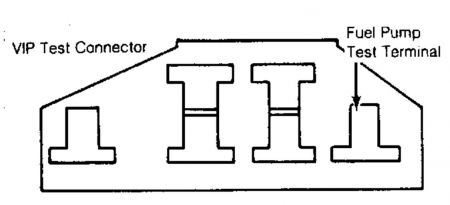
Test your pressure at rail as in the video, test tank pumps like this: In-Tank Reservoir (ITR) Fuel Pump Testing 1. Ensure fuel tank has adequate fuel. Turn ignition off. Install fuel pressure gauge. Install a test lead to Fuel Pump (FP) lead of VIP test connector. See Fig. 9 . Turn ignition on, engine off. Ground test lead to run fuel pump. Check fuel pressure. See FUEL PRESSURE SPECIFICATIONS . If fuel pressure is within specification, go to step 5). If fuel pressure is not within specification, go to next step. 2. If pressure is low, but greater than 3 PSI (21 kPa), go to next step. If pressure is not more than 3 PSI (21 kPa) go to step 4). 3. Check fuel system for: Ã Â Â Plugged fuel filter (replace filter and check again for proper pressure). Ã Â Â Kinked/restricted fuel lines (visual inspection). Ã Â Â Low voltage to fuel pump (should be within 0.5 volt of battery voltage at connector). Ã Â Â Disconnect return fuel line and note if fuel is being returned during this low pressure condition. If fuel is being returned, replace or adjust pressure regulator. If a problem was found, repair as necessary. After repair, go to step 1) and retest system. If a problem was not found, replace fuel pump and go to step 1) and retest system. 4. Check the following electrical circuit problems: Ã Â Â Ensure inertia switch is not open (reset switch as required). Ã Â Â Wiring at fuel pump/tank connector loose or open. Ã Â Â Fuel pump ground connection at chassis loose or defective. Ã Â Â Improper fuel pump relay operation (should operate when fuel pump test lead is grounded with the ignition key on). Ã Â Â EEC relay not operating if fuel pump relay doesn't operate. If a problem was found, repair as necessary. After repair, go to step 1) and retest system. If a problem was not found, replace fuel pump and go to step 1) and retest system. 5. Remove ground from test lead and note pressure on gauge. Pressure should remain within 2 PSI (14 kPa) for 3 minutes after lead is ungrounded. If pressure holds as specified, go to step 7). If pressure does not hold as specified, go to next step. 6. Check fuel lines and connectors for leakage. Disconnect fuel return line and plug engine side. Momentarily activate fuel pump by grounding test lead. Raise pressure to approximate operating pressure and repeat step 5). If pressure holds, replace pressure regulator and repeat step 5). If pressure decays rapidly, go to next step. If system still fails step 5), there may be a leaking fuel injector or rail. Repair as necessary and go to step 5). 7. If pressure decays rapidly enough that needle movement can be observed, replace ITR unit if equipped with a single tank. If equipped with dual tanks, go to next step. If pressure holds, go to step 10). 8. Remove fuel supply line from sender port of midship tank. Change pressure gauge from 5/16" to 3/8" adaptor to fit fuel line quick connector. Connect gauge to end of supply line removed from midship sender. Move the tank selector switch to REAR tank position. Turn ignition on and hold until fuel pump shuts itself off (approximately one second). Turn ignition off. Observe pressure gauge. If pressure holds steady, go to next step. If pressure does not hold steady, replace rear ITR unit and go to next step. 9. Remove fuel pressure gauge from supply line. Install a 3/8" right-angle quick-connector to pressure gauge. Connect gauge to midship tank ITR supply port. Move the tank selector switch to the FRONT tank position. Turn ignition to on position and hold until fuel pump shuts itself off (approximately one second). Turn ignition off. Observe pressure gauge. If pressure holds steady, midship ITR unit is okay. Remove fuel pressure gauge and reconnect all fuel lines. Go to step 1) to retest system. If pressure does not hold steady, replace midship ITR unit. Go to step 1 to retest system. 10. Disconnect and plug vacuum line connected to the pressure regulator. Start engine and run at idle. Check fuel pressure. See FUEL PRESSURE SPECIFICATIONS . If fuel pressure is within specification, go to step 12). If fuel pressure is not within specification, go to next step. 11. Check the following for cause of low pressure: Ã Â Â Fuel filter restriction. Ã Â Â Improper fuel regulator adjustment. Ã Â Â Fuel line restricted. Ã Â Â Improper voltage to fuel pump (battery voltage at pump connections). If a problem was found, repair as necessary. After repair, go to step 1) and retest system. If a problem was not found, replace fuel pump and go to step 1) and retest system. 12. With engine running at idle and vacuum line disconnected, note fuel rail pressure. Rapidly accelerate engine and watch fuel pressure. If pressure remains within 5 PSI of starting pressure, system is okay. If pressure does not remain within 5 PSI of starting pressure, go to step 11). FUEL PRESSURE REGULATOR 1. Relieve fuel pressure. See FUEL SYSTEM PRESSURE RELEASE . Connect fuel pressure gauge at Schrader valve. Start and operate engine for 10 seconds. Stop engine for 10 seconds. Start and operate engine for 10 seconds. Stop engine and remove pressure regulator vacuum hose. Check for fuel at vacuum port. 2. If fuel is present, replace fuel pressure regulator. If fuel is not present, start and operate engine for 30 seconds. Stop engine and check fuel pressure gauge. If gauge reading drops more than 5 psi (.35 kg/cm 2 ) in 60 seconds, disconnect and plug fuel return line at engine. Start and operate engine until normal fuel pressure is obtained. 3. Stop engine and check fuel pressure gauge. If gauge reading drops more than 5 psi (.35 kg/cm 2 ) in 30 seconds, replace high pressure fuel pump (dual pump system) or fuel sender/pump assembly (single pump type). If gauge does not drop more than 5 psi (.35 kg/cm 2 ) in 30 seconds, replace NOTE: Road testing vehicle while monitoring pressure may give a better test under load conditions. NOTE: For fuel pressure specifications, see FUEL PRESSURE SPECIFICATIONS article.


http://www.2carpros.com/forum/automotive_pictures/62217_VIP_Test_connector_1.jpg


http://www.2carpros.com/forum/automotive_pictures/62217_Fuel_pres_spec_1.jpg

Was this
answer
helpful?
Yes
No
+1
Tuesday, August 24th, 2010 AT 4:17 PM
Tiny
7777
  • MEMBER
  • 6 POSTS
I have a 4.9 inline 6 fuel pressure at the rail is 56psi with the front fuel tank and 58psi with the rear tank, I do have spark at the plugs, I will test the crank shaft sensor after the rain storm ends.
Was this
answer
helpful?
Yes
No
Wednesday, August 25th, 2010 AT 11:37 AM
Tiny
MERLIN2021
  • MECHANIC
  • 17,250 POSTS
Then this seems as if the injectors arent working, check cam sensor if it's got no distributor. Or ignition switch, crank position may be messed up in the switch not sending signal to the injectors to fire, or blown injector fuse, ign fuse or Pcm power relay.
Was this
answer
helpful?
Yes
No
Wednesday, August 25th, 2010 AT 1:47 PM
Tiny
7777
  • MEMBER
  • 6 POSTS
I agree with you that the injectors are not working. I think I was checking the wiring for voltage at the injectors correctlly. I disconnected the wiring at number one injector, turned on the ignition switch and check to see if it was hot (Actually both wires were hot, assuming that was because the rest of the injectors were still connected) then I had someone turn over the engine and check for flashing or pulsing or what ever the term is today. One side of the connector stayed a steady hot and the other side did flash, ever so sliightly. So does that mean that the injectors are getting the signal? Also it does have a distributor.
Was this
answer
helpful?
Yes
No
Thursday, August 26th, 2010 AT 8:10 AM
Tiny
MERLIN2021
  • MECHANIC
  • 17,250 POSTS
TEST H: STEP 5 5) Isolate Faulty Injector Circuit Turn key off. Install breakout box and disconnect ECA. Disconnect all injectors on suspect bank. With DVOM set on 200-ohm scale, connect one injector and measure resistance between test pins No. 37 and 58 or 59. Disconnect injector and repeat process for all other injectors. See TRUCK - INDIVIDUAL INJECTOR RESISTANCE table for specifications. If all injectors are within specifications, go to step 6). If injectors are not to specification, remove breakout box, reconnect ECA and injectors. Repair open or short in injector harness. If circuit is okay, replace injector. Rerun QUICK TEST. TEST H: STEP 6 6) Check Injector Drive Signal With key off and breakout box installed, connect ECA to breakout box. Use a non-powered 12-volt test light and the following connection procedure: PFI ENGINES Connect test light between test pins No. 37 and 58 at the breakout box. Connect light between test pins No. 37 and 59 at breakout box. SEQUENTIAL PFI ENGINES Connect test light between test pin No. 37 and the suspect injector(s) test pin at the breakout box. Crank or start engine. A properly operating system is indicated by a test light that glows dimly. If light glows dimly, go to next step; except on sequential PFI engines. On sequential PFI engine, remove breakout box and reconnect ECA. Clean and test injectors. Rerun QUICK TEST and CYLINDER BALANCE TEST. If test light does not glow dimly, perform the following procedure: Ã Â Â No Light - Check for 12 volts at test pins No. 37 and 57. Ã Â Â Bright Light - Check injector circuit for shorts to ground. If system is okay, remove breakout box and replace ECA. Remove breakout box, reconnect all components and repeat QUICK TEST.
The easiest way to check the circuit is with a NOID light they are cheap and plug right into the injector harness, it will flash as the engine is cranked. But the fact that power is at the injectors and seems to flash means if spark gas and compression is OK, the ECU may be defective. Compression has been checked? Timing? Test the ign switch to remove it as a suspect.
1. Before performing continuity tests, if an engine-won't-crank condition exists (with automatic transmission), determine if the condition exists with the shift lever in both Park and Neutral. If the no-crank problem occurs in only one shift position, the probable cause is the neutral start switch located on the transmission. 2. For an engine-won't-crank condition (with a manual transmission), verify that the clutch/starter interlock switch is working properly. Accessories that fail to operate with ignition switch in RUN position or that remain on when ignition is turned off, may be caused by a misadjusted switch rather than a malfunctioning switch. See ADJUSTMENTS in this article. 3. If previous tests disclose no problem, lower steering column and disconnect ignition switch connector. Test the switch continuity using a self-powered test light or ohmmeter. Continuity should not exist between any terminal and chassis ground, except circuits No. 41 and 977, in the START position only. See Fig. 1 . See the IGNITION SWITCH CONTINUITY TABLE for terminal identification.


http://www.2carpros.com/forum/automotive_pictures/62217_IGN_2.jpg


http://www.2carpros.com/forum/automotive_pictures/62217_IGNSW_2.jpg


http://www.2carpros.com/forum/automotive_pictures/62217_IGNA_1.jpg

Was this
answer
helpful?
Yes
No
Friday, August 27th, 2010 AT 6:58 PM
Tiny
7777
  • MEMBER
  • 6 POSTS
Most of the last request is over my head. I do have power at the injectors, so injector fuse is okay, I replaced the eec relay and ignition switch. I had only one code in the computer, but I lost that code that I had written down, tried to read codes again and all I get is vechile not responding. In thre previous messages I said I replaced the fuel pump relay because the fuel pumps are running all the time. I thought the relay shuts them off after a few moments?
Was this
answer
helpful?
Yes
No
Monday, August 30th, 2010 AT 8:38 AM
Tiny
MERLIN2021
  • MECHANIC
  • 17,250 POSTS
It does, but you will need to trace the hot wires to see if the relay is opening the ground to the pump. Some wire in there is shorted to ground, or the PCM could be faulty.
On the firewall on the passenger side check the ground wire.
Was this
answer
helpful?
Yes
No
Monday, August 30th, 2010 AT 4:27 PM
Tiny
7777
  • MEMBER
  • 6 POSTS
Well I have not found anything obvious with the electrical system on this truck, all the things that I check were within the specs. So I just suck up the cost of the pcm and replaced it. The truck starts and runs fine, the fuel pumps charge up the way they are suppose too and shuts off the way they are suppose too. I want to thank you for your input but it was the pcm all the time.
Was this
answer
helpful?
Yes
No
Friday, September 3rd, 2010 AT 3:49 PM
Tiny
MERLIN2021
  • MECHANIC
  • 17,250 POSTS
My posts mention the PCM several times, including the last one: osted at Mon Aug 30, 2010 4:27 pm
By merlin2021, Certified ASE Technician
(11913) Give Feedback | Votes: 173

It does, but you will need to trace the hot wires to see if the relay is opening the ground to the pump. Some wire in there is shorted to ground, or the PCM could be faulty.
On the firewall on the passenger side check the ground wire.
_________________
Was this
answer
helpful?
Yes
No
Saturday, September 4th, 2010 AT 10:49 AM

Please login or register to post a reply.

Sponsored links