AUTOMATIC LOCKING HUB
Removal
Raise and support vehicle. To remove locking hub assembly, first separate locking hub cap assembly from body assembly. Using Torx-R Bit (TX25), detach 5 cap screws from cap assembly, then remove locking hub cap and bearing components.
NOTE:DO NOT drop ball bearing, race, spring retainer or spring during disassembly.
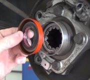
Remove rubber sealing ring. Remove seal bridge retainer (small metal stamping) from spring retainer ring space. Detach lock ring retainer by closing ends with needle-nose pliers while pulling locking hub body assembly from wheel hub.
If wheel hub and spindle are to be removed, detach "C" washer from stub shaft groove. Remove splined spacer from shaft. Remove wheel bearing lock nuts and lock washer. Disassemble, clean and inspect locking hub assembly components.
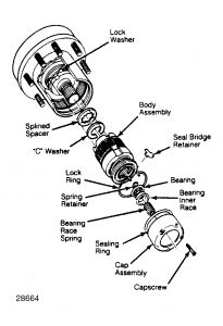
Fig. 1: Exploded View of Automatic Locking Hub
Courtesy of FORD MOTOR CO.
Detach snap ring and flat washer from inner end of locking hub assembly. Pull hub sleeve and attached parts out of drag sleeve, then cock drag sleeve to unlock tangs of brake band. Remove drag sleeve assembly.
CAUTION:DO NOT remove brake band from drag sleeve.
Wash drag sleeve/brake band assembly in clean solvent and thoroughly blow dry. Lubricate brake band/drag sleeve assembly with lubricant meeting specification ESL-M1C93A (Darmex Spec. DX-123-LT). Work lubricant over spring and area of drag sleeve under spring.
Dip locking hub body assembly (except cap assembly and brake band/drag sleeve assembly) in Dexron II ATF and permit to drip dry for a few minutes before proceeding with assembly.
Inspection
Wash locking hub cap bearing, race and retainer in clean solvent, then inspect for excessive wear or damage. Replace components as needed. Thoroughly blow dry parts with compressed air. DO NOT spin bearings with air or damage can result. Repack bearing with lithium grease, then properly position bearing assembly in race. See Fig. 2 .
Installation
To install locking hub components, first assemble one of 2 brake band tangs on each side of outer cage (plastic), which is located in window of inner cage (steel). It is necessary to cock these parts to engage tangs in this position as the drag sleeve is positioned against cam follower face. Install washer and snap ring.
If removed, install wheel bearing inner adjusting nut and lock washer. Tighten outer lock nut to 150 ft. lbs. (203 N.m). Install splined spacer and "C" washer onto axle shaft.
NOTE:Remove excess grease from hub lock and hub splines before installation.
Start locking hub assembly into hub. Ensure large tangs are lined up with lock washer and outside diameter and inside diameter splines are in line with hub and axle shaft splines.
Install retainer ring by closing ring ends with needle-nose pliers and, at the same time, push locking hub assembly into hub. Install seal bridge retainer (narrow end first).
Install rubber seal over locking hub. Install locking hub cap assembly. Ensure ball bearing, race, spring and retainer are in proper position. Tighten Torx-R bit screws to 40-50 INCH lbs. (4.5-5.6 N.m) following tightening sequence (tighten one, skip one, etc.) until complete.
MANUAL LOCKING HUB
Removal
To remove locking hub, first separate locking hub cap assembly from hub body assembly by removing 6 Allen cap screws from cap assembly, then slip components apart. Detach snap ring (retainer ring) from end of axle shaft.
Remove lock ring (seated in groove of wheel hub). See Fig. 3 . Slide hub body assembly out of wheel hub. If necessary, install 2 cap screws and pull body from out of hub.
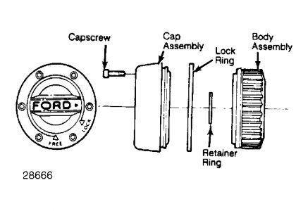
Fig. 3: Exploded View of Manual Locking Hub
Courtesy of FORD MOTOR CO.
NOTE:DO NOT pack grease into locking hub. Excess grease can cause an increase in dialing effort.
Installation
To install locking hub assembly components, reverse removal procedure. Install locking hub cap assembly and tighten cap screws to 40-60 INCH lbs. (4.5-6.0 N.m).
SPONSORED LINKS
Saturday, December 13th, 2008 AT 6:30 AM