LOWER CONTROL ARM, BALL JOINT & BUSHINGS
NOTE:Lower ball joints and bushings are an integral part of the lower control arm, and are replaced only as an assembly.
Removal
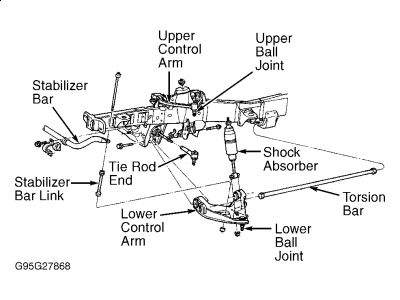
Place steering wheel and steering system in the centered position. Turn off air suspension switch (if equipped). Raise vehicle on hoist. Remove wheel and tire assembly. Disconnect stabilizer bar link from lower control arm. See Fig. 1 . Support lower control arm. Remove 2 shock absorber-to-lower control arm nuts. Remove shock absorber upper retaining nut, washer and insulator. Compress shock absorber, and remove from vehicle.
Place safety stands under jacking pads, and lower hoist while maintaining working room. Remove torsion bar. See TORSION BAR . Loosen front and rear lower control arm pivot bolts. Remove cotter pin and loosen, but DO NOT remove, lower ball joint-to-spindle nut. Using Pitman Arm Puller (T64P-3590-F), loosen lower ball joint in spindle.
Remove puller and lower ball joint-to-spindle nut. Raise lower control arm and separate lower ball joint from spindle. Remove front and rear lower control arm pivot bolts, and remove lower control arm from vehicle. Inspect lower ball joints and boot seals. Replace lower control arm assembly to service ball joints and bushings (if necessary).
Installation
Position lower control arm in crossmember, and install pivot bolts. Install nuts on pivot bolts, and tighten until snug. Install torsion bar. See TORSION BAR . Raise lower control arm to position lower ball joint into spindle. Install NEW lower ball joint-to-spindle nut and tighten to specification. See TORQUE SPECIFICATIONS .
Install NEW cotter pin toward engine compartment. Ensure head of cotter pin is facing tire. Ensure fingers of cotter pin are bent at a right angle to secure. Place shock absorber into position. Install insulator, washer and nut onto stud. Tighten nut to specification. Install 2 lower shock absorber retaining nuts, and tighten to specification. Install wheel and tire assembly. Lower vehicle to normal ride height.
Connect stabilizer bar link-to-lower control arm, and tighten nut to specification. Tighten lower control arm pivot bolts to specification. Check ride height. See RIDE HEIGHT under ADJUSTMENTS & INSPECTION. Check wheel alignment. See appropriate SPECIFICATIONS & PROCEDURES article in WHEEL ALIGNMENT.

Mar 6, 2009 at 9:48 AM
