Speedometer problems?

Tiny
ASHKAT92
  • MEMBER
  • 2000 FORD ESCORT
  • 4 CYL
  • FWD
  • AUTOMATIC
  • 112,556 MILES
Today my speedometer, odometer and trip odometer stopped working. But everything on the instrument cluster is working as far as I can tell. Do you think it could be a fuse or something else? Hopefully small and inexpensive since I have limited money. Please help.
Thursday, January 15th, 2009 AT 6:19 PM

59 Replies

Tiny
DAVE H
  • MECHANIC
  • 13,383 POSTS
SPEEDOMETER/ODOMETER INACCURATE

Sedan & Wagon
Turn ignition off. Connect scan tool and retrieve Diagnostic Trouble Codes (DTC) following manufacturer's instructions. If no DTCs are present, go to next step. If DTCs are present, see appropriate SELF-DIAGNOSTICS article in ENGINE PERFORMANCE. Repair DTCs as necessary, then retest system.
Using scan tool, observe Vehicle Speed Sensor (VSS) output Parameter Identification (PID) while assistant drives vehicle over range of speeds on various road surfaces. If VSS PID varies smoothly with vehicle speed, go to next step. If VSS PID does not vary or is erratic, see appropriate SELF-DIAGNOSTICS article in ENGINE PERFORMANCE to diagnose VSS.
Remove and check OBDII 10-amp fuse in engine compartment fuse box. If fuse is okay, reinstall fuse and go to step 5. If fuse is blown, go to next step.
Turn ignition off. Remove instrument cluster. See INSTRUMENT CLUSTER under REMOVAL & INSTALLATION. Disconnect all instrument cluster electrical connectors. Measure resistance between ground and instrument cluster harness connector C252 terminal No. 12 (Green wire). See Fig. 6. Measured resistance should be more than 10 k/ohms. If resistance is more than 10 k/ohms, replace OBDII 10-amp fuse and go to next step. If resistance is less than 10 k/ohms, repair short to ground in Green wire between instrument cluster harness connector and fuse. See WIRING DIAGRAMS.
Turn ignition off. Remove instrument cluster. See INSTRUMENT CLUSTER under REMOVAL & INSTALLATION. Disconnect instrument cluster electrical connectors. Measure voltage between ground and instrument cluster harness connector C252 terminal No. 12 (Green wire). See Fig. 6. Voltage should be more than 10 volts. If voltage is more than 10 volts, go to next step. If voltage is less than 10 volts, repair short to voltage in Green wire between instrument cluster harness connector and fuse. See WIRING DIAGRAMS.
Turn ignition off. Disconnect Vehicle Speed Sensor (VSS) harness connector C132. Measure resistance of Blue wire between VSS harness connector and instrument cluster harness connector C252 terminal No. 7. See Fig. 6. Measure resistance of White/Black wire between VSS harness connector C132 and instrument cluster harness connector C253 terminal No. 9. Resistance in both tests should be less than 5 ohms. If resistances are as specified, go to next step. If resistances are not as specified, repair open in White/Black or Blue wire. See WIRING DIAGRAMS.
Measure resistance between ground and instrument cluster harness connector C253 terminal No. 9 (White/Black wire). Resistance should be more than 10 k/ohms. If measured resistance is more than 10 k/ohms, go to next step. If resistance is less than 10 k/ohms, repair short to ground in White/Black wire.
Turn ignition on. Measure voltage between ground and instrument cluster harness connector C252 terminals No. 8 and 4 (Black/Yellow wire). See Fig. 6. Voltage should be more than 10 volts. If voltage is more than 10 volts, go to next step. If voltage is less than 10 volts, repair short to voltage in Black/Yellow wire between instrument cluster connector and fuse. See WIRING DIAGRAMS.
Turn ignition off. Visually inspect instrument cluster printed circuit for damage, cracks or hot spots. If instrument cluster printed circuit is okay, replace speedometer. If instrument cluster printed circuit is damaged, replace printed circuit and gauge contact clips. See PRINTED CIRCUIT under REMOVAL & INSTALLATION.
TEST E: TACHOMETER INACCURATE
Sedan & Wagon
Using scan tool, observe RPM output Parameter Identification (PID) over range of engine speeds. If RPM PID varies smoothly with vehicle RPM, vehicle is okay. If RPM PID does not vary or is erratic, see appropriate SELF-DIAGNOSTICS article in ENGINE PERFORMANCE to diagnose Clean Tach Output (CTO) circuit. If only tachometer is inaccurate or inoperative, go to next step.
Turn ignition off. Remove instrument cluster. See INSTRUMENT CLUSTER under REMOVAL & INSTALLATION. Disconnect instrument cluster electrical connector C253. See Fig. 7 or Fig. 8. Turn ignition on. Measure voltage between ground and instrument cluster harness connector C253 terminal No. 8 (Black/Yellow wire). Voltage should be more than 10 volts. If voltage is more than 10 volts, go to next step. If voltage is less than 10 volts, repair short to voltage in Black/Yellow wire between instrument cluster connector and fuse. See WIRING DIAGRAMS.
Turn ignition off. Measure resistance between ground and instrument cluster harness connector C253 terminal No. 7 (Black/Green wire). See Fig. 7 or Fig. 8. Resistance should be less than 5 ohms. If resistance is less than 5 ohms, go to next step. If resistance is more than 5 ohms, repair open in Black/Green wire between instrument cluster connector and ground. See WIRING DIAGRAMS.
Visually inspect instrument cluster printed circuit for damage, cracks or hot spots. If instrument cluster printed circuit is okay, go to next step. If instrument cluster printed circuit is damaged, replace printed circuit and gauge contact clips. See PRINTED CIRCUIT under REMOVAL & INSTALLATION.
Install EEC-V 104-pin Breakout Box (014-00950) following manufacturer's instructions. Measure resistance between breakout box terminal No. 48 and instrument cluster harness connector C253 terminal No. 6 (Light Green/Red wire). See Fig. 7 or Fig. 8. Resistance should be less than 5 ohms. Measure resistance between ground and instrument cluster harness connector C253 terminal No. 6 (Light Green/Red wire). Resistance should be more than 10 k/ohms. If both resistances are as specified, see appropriate SELF-DIAGNOSTICS article in ENGINE PERFORMANCE to diagnose Clean Tach Output (CTO) circuit. If resistances are not as specified, repair open in Light Green/Red wire. See WIRING DIAGRAMS
Was this
answer
helpful?
Yes
No
Thursday, January 15th, 2009 AT 7:53 PM
Tiny
BARRIE99
  • MEMBER
  • 1 POST
  • 1999 FORD ESCORT
  • 4 CYL
  • FWD
  • MANUAL
  • 175,000 MILES
The speedometer stopped working and the check engine light came on at the same time. Tach is working fine. What can be the problem?
Was this
answer
helpful?
Yes
No
+1
Sunday, July 26th, 2020 AT 10:54 AM (Merged)
Tiny
RASMATAZ
  • MECHANIC
  • 75,992 POSTS
Get the computer scanned for code/s due to the CEL is On this is your starting point on finding out what's causing the CEL to come on. Could be the vehicle speed sensor. Autozone provides this service free.
Was this
answer
helpful?
Yes
No
Sunday, July 26th, 2020 AT 10:54 AM (Merged)
Tiny
BIGHONKER
  • MEMBER
  • 1 POST
  • 1999 FORD ESCORT
  • 4 CYL
  • FWD
  • AUTOMATIC
  • 104,000 MILES
I own a 1999 Ford Escort. The speedometer doesn't work. I had it checked and the speed sensor code came up so I attempted to replace it. I removed the mounting bracket but the sensor itself is corroded into place so bad it won't budge. I soaked with WD 40 overnight but still no go. I broke the male end of the plug off the top beating on it. There is very limited space to work on it. Is there any way to access the sensor where there is enough room to manipulate it?
Was this
answer
helpful?
Yes
No
Sunday, July 26th, 2020 AT 10:54 AM (Merged)
Tiny
MASTERTECHTIM
  • MECHANIC
  • 4,749 POSTS
Unfortunately this is one situation noone likes being in and there is no easy way out. I use pb blaster its like a penetrating oil I find works better that wd 40 on these situations. Try moving the sensor side to side(rotating) until you can get it to move, patience is the key, you dont want to damage anymore because you need the sensor hanging out a little for something to hold to turn and pull. Sorry there is no short cuts, this job stinks.
Was this
answer
helpful?
Yes
No
Sunday, July 26th, 2020 AT 10:54 AM (Merged)
Tiny
BRIANSTRONG
  • MEMBER
  • 7 POSTS
I just had this same exact problem with my 95 escort the solution is simble but a pain in the butt
Douse the oem or the aluminum left with pb blaster
go under the car on the back of the sencor it sticks out about one centimeter use a good sharp chisel and a hamer put the chisel right under the lip and smack it hard may have to do it a few times but it should pop loose
hope this helps it took me two days to find a good spot to get it out from
Was this
answer
helpful?
Yes
No
+1
Sunday, July 26th, 2020 AT 10:54 AM (Merged)
Tiny
RICK 08
  • MEMBER
  • 54 POSTS
Since some time has passed I expect you have resolved the problem. If not...
I used thredded rod & a tap to fabricate a slide hammer tapping into the aluminum shaft if the sensor. Out it came, nothing else worked.
Was this
answer
helpful?
Yes
No
Sunday, July 26th, 2020 AT 10:54 AM (Merged)
Tiny
MARINDA0510
  • MEMBER
  • 3 POSTS
  • FORD ESCORT
I drive a 1999 Ford Escort ZX2 with 149000 miles, 2.0 L engine, automatic tranny. When I'm driving and get to exactly 45 mph it sticks. So I hit the panel, I know probably not the best idea, and it will jump to in the 50s but it sticks there and hitting it doesn't really help. Once it comes unstuck, I'm usually going 60 or so. If I keep it above 55 or below 45 it has NO problems. Plus, a couple times a week, I only notice at night but sometimes the instrument cluster light will go out. Everything still works (no digital by the way) and the needles are still lit up. Also, I do have a different cluster that has a light I can switch on and off if that makes a difference. But thee thing is, it only does it when I have my XM radio plugged in. It uses the cigarette lighter for power. Only that though, my cell phone charger has no effect on it. Hope someone can help! Sorry if confusing, easier if spoken!
Was this
answer
helpful?
Yes
No
Sunday, July 26th, 2020 AT 10:55 AM (Merged)
Tiny
MARINDA0510
  • MEMBER
  • 3 POSTS
It's the same cluster that came with the car but the previous owner put in a new background that has flames and there is a switch to turn another light on and off. That's all that I know. And it was just a coincidence I guess with the XM because I tried not having it on at all yesterday and today and it still did it.
Was this
answer
helpful?
Yes
No
Sunday, July 26th, 2020 AT 10:55 AM (Merged)
Tiny
MARINDA0510
  • MEMBER
  • 3 POSTS
Thank you i'm probably just going to go back to normal but I have no idea how! Ha!
Was this
answer
helpful?
Yes
No
Sunday, July 26th, 2020 AT 10:55 AM (Merged)
Tiny
GOT2RAMBLE
  • MEMBER
  • 1 POST
  • 1999 FORD ESCORT
  • 4 CYL
  • FWD
  • AUTOMATIC
  • 11,500 MILES
Sometimes when I am at highway speed (65 mph ) the speedometer will stop working only to come back to life while driving in town at 25 mph. This has occurred several times and the last time the check engine light came on at the same time that the speedometer quit working. The car does have an after market cruise control that was installed by the dealer several years ago.
Was this
answer
helpful?
Yes
No
Sunday, July 26th, 2020 AT 10:55 AM (Merged)
Tiny
DAVE H
  • MECHANIC
  • 13,383 POSTS
Hello. Thanks for the donation. Much appreciated

Check the wiring and check/clean or repalce the VSS (vehicle speed sensor). Hope this helps. Let me know !

Sedan & Wagon
Turn ignition off. Connect scan tool and retrieve Diagnostic Trouble Codes (DTC) following manufacturer's instructions. If no DTCs are present, go to next step. If DTCs are present, see appropriate SELF-DIAGNOSTICS article in ENGINE PERFORMANCE. Repair DTCs as necessary, then retest system.
Using scan tool, observe Vehicle Speed Sensor (VSS) output Parameter Identification (PID) while assistant drives vehicle over range of speeds on various road surfaces. If VSS PID varies smoothly with vehicle speed, go to next step. If VSS PID does not vary or is erratic, see appropriate SELF-DIAGNOSTICS article in ENGINE PERFORMANCE to diagnose VSS.
Remove and check OBDII 10-amp fuse in engine compartment fuse box. If fuse is okay, reinstall fuse and go to step 5. If fuse is blown, go to next step.
Turn ignition off. Remove instrument cluster. See INSTRUMENT CLUSTER under REMOVAL & INSTALLATION. Disconnect all instrument cluster electrical connectors. Measure resistance between ground and instrument cluster harness connector C252 terminal No. 12 (Green wire). See Fig. 6. Measured resistance should be more than 10 k/ohms. If resistance is more than 10 k/ohms, replace OBDII 10-amp fuse and go to next step. If resistance is less than 10 k/ohms, repair short to ground in Green wire between instrument cluster harness connector and fuse. See WIRING DIAGRAMS.
Turn ignition off. Remove instrument cluster. See INSTRUMENT CLUSTER under REMOVAL & INSTALLATION. Disconnect instrument cluster electrical connectors. Measure voltage between ground and instrument cluster harness connector C252 terminal No. 12 (Green wire). See Fig. 6. Voltage should be more than 10 volts. If voltage is more than 10 volts, go to next step. If voltage is less than 10 volts, repair short to voltage in Green wire between instrument cluster harness connector and fuse. See WIRING DIAGRAMS.
Turn ignition off. Disconnect Vehicle Speed Sensor (VSS) harness connector C132. Measure resistance of Blue wire between VSS harness connector and instrument cluster harness connector C252 terminal No. 7. See Fig. 6. Measure resistance of White/Black wire between VSS harness connector C132 and instrument cluster harness connector C253 terminal No. 9. Resistance in both tests should be less than 5 ohms. If resistances are as specified, go to next step. If resistances are not as specified, repair open in White/Black or Blue wire. See WIRING DIAGRAMS.
Measure resistance between ground and instrument cluster harness connector C253 terminal No. 9 (White/Black wire). Resistance should be more than 10 k/ohms. If measured resistance is more than 10 k/ohms, go to next step. If resistance is less than 10 k/ohms, repair short to ground in White/Black wire.
Turn ignition on. Measure voltage between ground and instrument cluster harness connector C252 terminals No. 8 and 4 (Black/Yellow wire). See Fig. 6. Voltage should be more than 10 volts. If voltage is more than 10 volts, go to next step. If voltage is less than 10 volts, repair short to voltage in Black/Yellow wire between instrument cluster connector and fuse. See WIRING DIAGRAMS.
Turn ignition off. Visually inspect instrument cluster printed circuit for damage, cracks or hot spots. If instrument cluster printed circuit is okay, replace speedometer. If instrument cluster printed circuit is damaged, replace printed circuit and gauge contact clips. See PRINTED CIRCUIT under REMOVAL & INSTALLATION.
Was this
answer
helpful?
Yes
No
Sunday, July 26th, 2020 AT 10:55 AM (Merged)
Tiny
OZZX2
  • MEMBER
  • 7 POSTS
  • 1999 FORD ESCORT
  • 4 CYL
  • FWD
  • AUTOMATIC
  • 72,000 MILES
Hello. My speedometer/odometer quit working. Started working intermittently for about two weeks, then stopped working completely. P0500 code. I swapped out VSS (new), two times instrument clusters (used), PCM (used).

Any other suggestions or troubleshooting steps I can try? Someone suggested it might be a ground issue.

Thanks.
Was this
answer
helpful?
Yes
No
Sunday, July 26th, 2020 AT 10:55 AM (Merged)
Tiny
OBXAUTOMEDIC
  • MECHANIC
  • 3,711 POSTS
Hello,

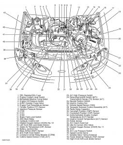
The only sensor you have not changed that is the most likely cause is the Turbine Speed Sensor. I cannot find a good diagram that show exactly were it is located. But here is a diagram that will give you a good idea. In the diagram it is labeled #22.


https://www.2carpros.com/forum/automotive_pictures/188069_99exscortzx2turbspeedsensr_1.jpg


press CTRL + to zoom in...

.
Was this
answer
helpful?
Yes
No
+2
Sunday, July 26th, 2020 AT 10:55 AM (Merged)
Tiny
OZZX2
  • MEMBER
  • 7 POSTS
Even though it gave a P0500 code, it could be the PO715 Turbine Speed Sensor?

This started happening a few days after I drove the car home with a broken belt tension er. It did not overheat since it was cold, but it ran the battery way down.
Was this
answer
helpful?
Yes
No
Sunday, July 26th, 2020 AT 10:55 AM (Merged)
Tiny
OZZX2
  • MEMBER
  • 7 POSTS
I took these pictures from the location of your diagram.

Are one of these the turbine/input speed sensor?


https://www.2carpros.com/forum/automotive_pictures/554052_ZX23_1.jpg


https://www.2carpros.com/forum/automotive_pictures/554052_ZX22_1.jpg


https://www.2carpros.com/forum/automotive_pictures/554052_ZX21_2.jpg

Was this
answer
helpful?
Yes
No
+3
Sunday, July 26th, 2020 AT 10:55 AM (Merged)
Tiny
OBXAUTOMEDIC
  • MECHANIC
  • 3,711 POSTS
I am sorry for delay in getting back been very busy.

Anyway, I believe it is the top picture.

The bottom picture is the transmission range selector switch.

Not sure about the center picture.

.
Was this
answer
helpful?
Yes
No
Sunday, July 26th, 2020 AT 10:55 AM (Merged)
Tiny
OZZX2
  • MEMBER
  • 7 POSTS
I swapped out the turbine/input speed sensor today and no change. I also tried another VSS and no change. I traced the wire and the middle picture goes to the oxygen sensor.

Any other ideas for troubleshooting? Seems like I lost the horn around the same time as the speedometer. Maybe a ground issue?

240 ohms at VSS. 230 ohms at dash (from what I have found, within proper range).

Hooked up multimeter/Ohm meter to the VSS wires at the cluster and drove it. It starts beeping faster (continuity) as you go faster (hall effect sensor).

Do you have a wiring diagram for the instrument cluster?
Was this
answer
helpful?
Yes
No
-1
Sunday, July 26th, 2020 AT 10:55 AM (Merged)
Tiny
AGAGAL
  • MEMBER
  • 2 POSTS
  • 1999 FORD ESCORT
  • 4 CYL
  • FWD
  • AUTOMATIC
  • 99,000 MILES
My husband purchased the vehicle and replaced the transmission which was removed and placed in the truck by the dealership because previous owner did not want to replace transmission. Anyway the vehicle runs great our only issue is that we can not locate WHERE the speedometer cable comes out of the firewall. We can find where it goes on the trans axle. Would it be possible that they removed the whole cable when they removed trany? All diagrams that we have only show where it attaches not where it comes from. Thank you so much.
Was this
answer
helpful?
Yes
No
Sunday, July 26th, 2020 AT 10:55 AM (Merged)
Tiny
RASMATAZ
  • MECHANIC
  • 75,992 POSTS
The reason why you couldn't find it -is its electronic not cable driven
Was this
answer
helpful?
Yes
No
Sunday, July 26th, 2020 AT 10:55 AM (Merged)

Please login or register to post a reply.

Sponsored links