NOTE : Before removing nozzle assemblies, clean exterior of each nozzle assembly and the surrounding area with solvent to prevent entry of dirt into engine when nozzle assemblies are removed. Also, clean fuel inlet and fuel leak-off piping connections. Blow dry with compressed air.
Remove and cap line sensor on number 4 cylinder to permit removal of fuel leak-off tee.
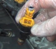
REMOVAL
Disconnect nozzle fuel inlet (high pressure) and fuel leak-off tees from each nozzle assembly and position out of the way. Cover open ends of fuel inlet lines and nozzles to prevent entry of dirt with fuel system protective cap set.
Remove fuel leak-off lines as an assembly.
Remove pump to fuel return tube hose at fuel return elbow cap elbow at pump. Disconnect hose (from leak-off tee of fuel filter) at leak-off tee.
Loosen two fuel return tube retaining clamps, one at intake manifold and one at engine lifting eye. Remove fuel return hose clamp at CDR valve bracket.
With clamps removed, remove return lines and tees as an assembly by lifting tees off nozzles.
Remove injection nozzles by turning counterclockwise. Pull nozzle assembly with copper washer from engine. Be careful not to strike nozzle tip against any hard surface during removal. Cover nozzle assembly fuel inlet opening and nozzle tip with plastic cap to prevent entry of dirt, fuel system protective cap set.
NOTE: Remove copper injector nozzle gasket from nozzle bore with O-Ring tool T71P-19703-C or equivalent if not attached to the nozzle tip.
Nozzle Holding Fixture
Place nozzle assemblies in a fabricated holder as they are removed from the heads. The holds should be marked with numbers corresponding to the cylinder numbering of the engine. Use of this holder permits nozzle installation into original location in the cylinder heads.
INSTALLATION
Thoroughly clean nozzle bore in cylinder head before reinserting nozzle assembly with nozzle seat cleaner. Pay particular attention to seating surface, in order that no small particles of metal or carbon will cause assembly to be cocked or permit blow-by of combustion gases. Blow out particles with compressed air.
Remove protective cap and install a new copper gasket nozzle assembly, with a small dab of Polyethylene grease.
NOTE : Anti-Seize Compound should be used on nozzle threads to aid installation and future removal.
Install nozzle assembly into cylinder head nozzle bore.
CAUTION : Be careful that nozzle tip does not strike against recess wall.
Tighten nozzle assembly to 35 ft lb (47 Nm).
Remove protective caps from nozzle assemblies and fuel lines.
Install leak-off tees and lines as an assembly by lowering onto nozzles. Connect clip and hose to fuel return elbow at pump. Install line to retaining clamps.
NOTE : Install two new O-ring seals for each fuel return tee.
Connect high pressure fuel line(s) and tighten to 22 ft lb (30 Nm) using fuel line nut wrench.
Start engine.
If necessary, purge high-pressure fuel lines of air by loosening connector one-half to one turn and cranking engine until bubble-free fuel flows from connection.
WARNING: Keep eyes and hands away from fuel spray. Fuel spraying from partially opened connections under high pressure can penetrate the skin and cause infection. Medical attention should be provided immediately in the event of skin penetration.
Check for fuel leakage at high-pressure connections.
SPONSORED LINKS
Tuesday, September 14th, 2010 AT 10:39 PM