TIPM replacement ABS, ESP light came on?

Tiny
KURTK
  • MEMBER
  • 2010 DODGE RAM
  • 5.7L
  • V8
  • 4WD
  • 102,000 MILES
ABS, ESP light came on, service 4wd light came on, traction control light came on. Won’t shift out of park. Is it an ABS sensor?
Thursday, March 21st, 2019 AT 12:25 PM

26 Replies

Tiny
JACOBANDNICKOLAS
  • MECHANIC
  • 108,133 POSTS
Welcome to 2CarPros.

This happens when the TIPM goes out but fear not it is easy to replace because it self initializes, but to be sure lets do a CAN scan which is the future of automotive repair you can get a CAN scanner from Amazon for about $50.00 here is a video to show you how.

https://youtu.be/u-4syLc-ifQ

here are the instructions in the diagrams below. Check out the diagrams (Below). Please let us know if you need anything else to get the problem fixed.
Was this
answer
helpful?
Yes
No
-1
Thursday, March 21st, 2019 AT 8:00 PM
Tiny
JASON BEVANS
  • MEMBER
  • 8 POSTS
  • 2010 DODGE RAM
  • 5.7L
  • V8
  • 4WD
  • AUTOMATIC
  • 60,000 MILES
Is the fuel pump fuse (m22) in my truck supposed to have constant 12 volts with the key in the off position?
Was this
answer
helpful?
Yes
No
Wednesday, June 23rd, 2021 AT 3:26 PM (Merged)
Tiny
ASEMASTER6371
  • MECHANIC
  • 52,797 POSTS
Good afternoon.

Yes, there will be power for the load side of the relay all the time.

Are you having an issue with the fuel pump?
Roy
Was this
answer
helpful?
Yes
No
+2
Wednesday, June 23rd, 2021 AT 3:26 PM (Merged)
Tiny
JASON BEVANS
  • MEMBER
  • 8 POSTS
Yeah, the fuel pump is not working.
I have been doing research on the fuel pump circuit for Dodge Rams 2009 - 2017
In the 2011 Dodge Ram the fuel pump fuse (m27) only seems to get power when the key is turned to the on position. The fuel pump relay seems to be a common problem on these trucks, they get stuck open and stop delivering power to the fuel pump fuse (m27).

I thought it would be the same thing in a 2010 Dodge Ram too. But from what your saying, I guess not. So the (m22) fuel pump fuse in a 2010 Dodge Ram TPIM is energized 24/7?
Was this
answer
helpful?
Yes
No
-2
Wednesday, June 23rd, 2021 AT 3:26 PM (Merged)
Tiny
ASEMASTER6371
  • MECHANIC
  • 52,797 POSTS
I sent a better picture for you to view.

The PCM controls the ground of the pump but the TIPM controls power to the control side. It sounds like the TIPM is going out which is common. Here are diagrams below to help you change it out which is easy because it self initiates. Check out the diagrams (Below). Please let us know what you find.
Was this
answer
helpful?
Yes
No
+2
Wednesday, June 23rd, 2021 AT 3:26 PM (Merged)
Tiny
JASON BEVANS
  • MEMBER
  • 8 POSTS
Thank you so much, this makes more sense now.
So I guess on a 2011 Dodge Ram things must be a little different?
The fuel pump relay feeds power to the fuel pump fuse (m25) instead of the other way around on a 2010 Dodge Ram the (m22) fuse feeds the relay?

Here is the YouTube video I was watching about bypassing the fuel pump relay

https://youtu.be/XPHBReUqsfs

I made a mistake earlier I was calling the fuel pump fuse the (m27) circuit it is actually (m25) in a 2011 Dodge Ram now that I have watched the video again.
Was this
answer
helpful?
Yes
No
Wednesday, June 23rd, 2021 AT 3:26 PM (Merged)
Tiny
RICK808
  • MEMBER
  • 1 POST
  • 2007 DODGE RAM
  • 6 CYL
  • 2WD
  • AUTOMATIC
  • 59,000 MILES
When started cold the lights, heater fan ect. Go dim/low then bright/high until truck is completely warmed up. The charge meter on the dash moves from low voltage to charging ie dim/bright and is always in charging position when truck is completely warmed up. The truck has 2 batteries. If I turn the truck off for 10-15 minutes it does the same thing. They say the TIPM is bad soI need to replace it.
Was this
answer
helpful?
Yes
No
Wednesday, June 23rd, 2021 AT 3:26 PM (Merged)
Tiny
DELGADOSR
  • MEMBER
  • 1 POST
Here is how to replace the TIPM it is easy because it self initializes. Check out the diagrams (Below). Please let us know if you need anything else to get the problem fixed.
Was this
answer
helpful?
Yes
No
Wednesday, June 23rd, 2021 AT 3:26 PM (Merged)
Tiny
ASEMASTER6371
  • MECHANIC
  • 52,797 POSTS
Okay, first, you never do that and leave it that way.

Second he used the wrong gauge wire doing that even though he was testing. That could damage the TIPM/

Lastly, he never verified power to the relay for the operation which is what any qualified tech would test first.

Roy
Was this
answer
helpful?
Yes
No
+2
Wednesday, June 23rd, 2021 AT 3:26 PM (Merged)
Tiny
JASON BEVANS
  • MEMBER
  • 8 POSTS
Thank you you have been very helpful.
Yeah, all the videos I have been watching say this is not a proper fix by any means.
Proper fix if it is the fuel pump relay is to replace entire TIPM ($1,100.00).
Or repairing TIPM by soldering on a new relay.

So it would seem the fuel pump system between 2010 and 2011 are slightly different.
2010 the fuel pump relay is fed power through the fuse.
2011 the fuel pump relay feeds the fuse power, allowing you to bypass the relay if you really wanted to.
Was this
answer
helpful?
Yes
No
-1
Wednesday, June 23rd, 2021 AT 3:26 PM (Merged)
Tiny
ASEMASTER6371
  • MECHANIC
  • 52,797 POSTS
No, the 11 does not feed the fuse. The control side is controlled by the TIPM. The load side is fed from the ignition switch.
Was this
answer
helpful?
Yes
No
Wednesday, June 23rd, 2021 AT 3:26 PM (Merged)
Tiny
JASON BEVANS
  • MEMBER
  • 8 POSTS
So the ignition switch does not turn the fuel pump relay on, then give power to the fuse? (M25)
Was this
answer
helpful?
Yes
No
-1
Wednesday, June 23rd, 2021 AT 3:26 PM (Merged)
Tiny
ASEMASTER6371
  • MECHANIC
  • 52,797 POSTS
No, the TIPM controls the control side of the relay. The load side power is provided from power from the ignition.

Roy
Was this
answer
helpful?
Yes
No
Wednesday, June 23rd, 2021 AT 3:26 PM (Merged)
Tiny
JASON BEVANS
  • MEMBER
  • 8 POSTS
Thank you for answering my questions you have been very helpful. It was the TIPM I wish I listened sooner DOH.
Was this
answer
helpful?
Yes
No
-1
Wednesday, June 23rd, 2021 AT 3:26 PM (Merged)
Tiny
ALTASNOWMAN
  • MEMBER
  • 39 POSTS
  • 2002 DODGE RAM
  • 4.7L
  • V8
  • 2WD
  • AUTOMATIC
  • 122,000 MILES
And how do I disconnect the wiring harnesses? As I have not done this type of thing in over 35 years.
Was this
answer
helpful?
Yes
No
Wednesday, June 23rd, 2021 AT 3:26 PM (Merged)
Tiny
ASEMASTER6371
  • MECHANIC
  • 52,797 POSTS
You are welcome.

Always glad to help.

Roy
Was this
answer
helpful?
Yes
No
-1
Wednesday, June 23rd, 2021 AT 3:26 PM (Merged)
Tiny
KEN L
  • MASTER CERTIFIED MECHANIC
  • 42,840 POSTS
Hello,

This is an easy repair because the TIPM self initializes. Here are instructions on how to do the job in the diagrams below. Check out the diagrams (below). Please let us know what happens.
Was this
answer
helpful?
Yes
No
+1
Wednesday, June 23rd, 2021 AT 3:26 PM (Merged)
Tiny
TURTLE1980
  • MEMBER
  • 6 POSTS
  • 2002 DODGE RAM
  • 4.9L
  • V8
  • 2WD
  • AUTOMATIC
  • 272,188 MILES
I am having issues with my lights and when I checked my fuses they were good, but I am not getting power to the individual slots for the lights themselves, but still are getting power to the rest of the fuses.
Was this
answer
helpful?
Yes
No
-1
Wednesday, June 23rd, 2021 AT 3:27 PM (Merged)
Tiny
JACOBANDNICKOLAS
  • MECHANIC
  • 108,133 POSTS
These vehicles have what is called a TIPM, totally integrated power module, which is under the fuse box under the hood. What happens is this. There are several plug connections to the module all of which have very small pins. What I have been seeing happen is this. The pins, which are very thin, corrode, and either lose connection or corrode and partially break.

The result is you still have power to the component, but when a load is placed on the circuit, it can't handle the load and fails.

In this case, I don't know if there is one light, both, high or low beam issues. So I am going to give you the directions for removal of the TIPM. Once you remove it, check the plug and pins I tell you to. The attached pictures correlate with the directions.

INTEGRATED POWER MODULE

REMOVAL
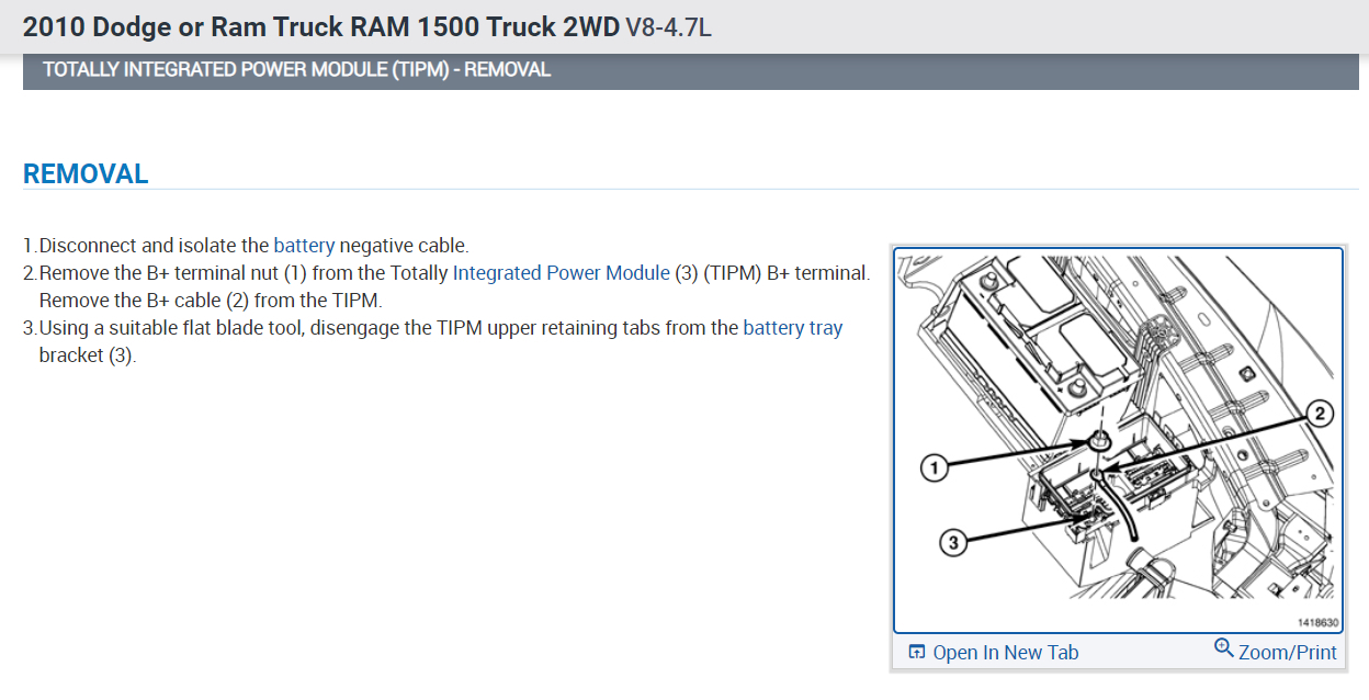
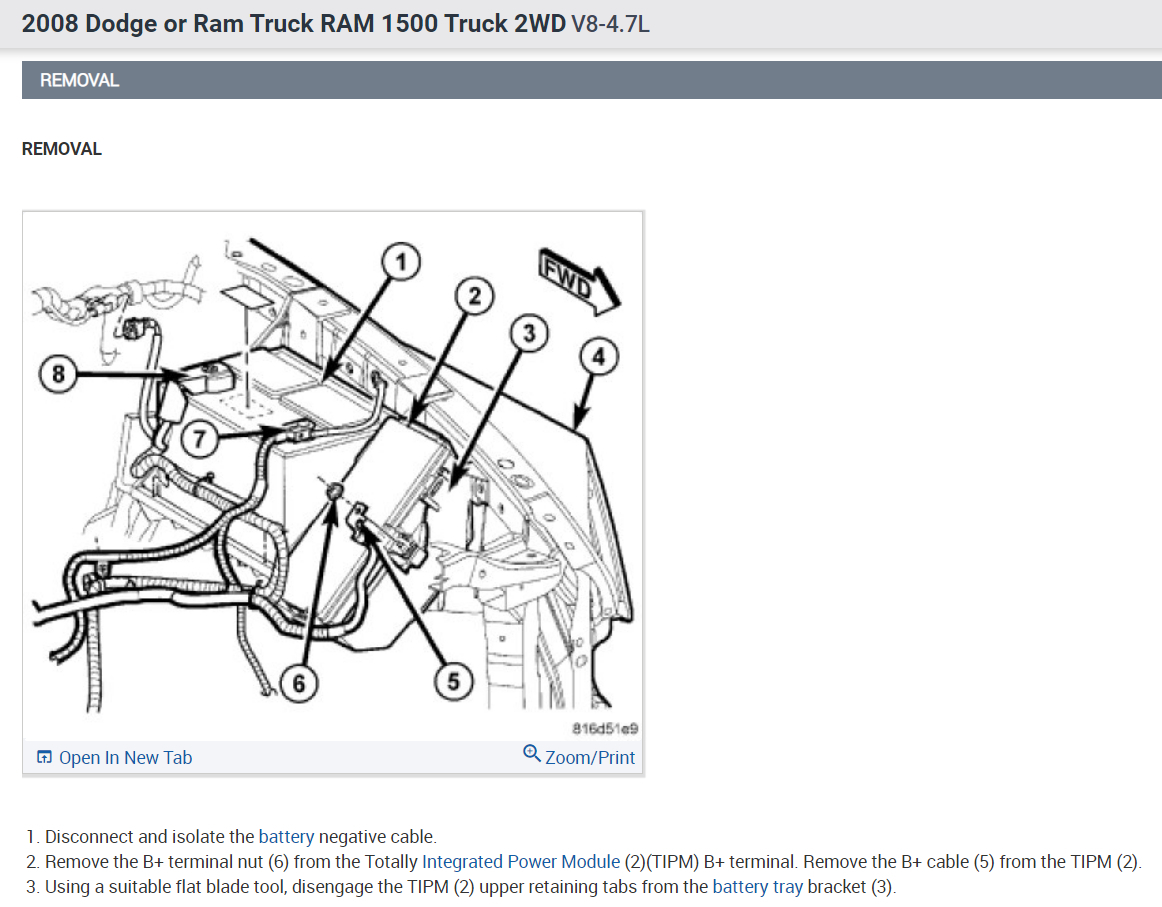
1. Disconnect the negative and positive battery cables.
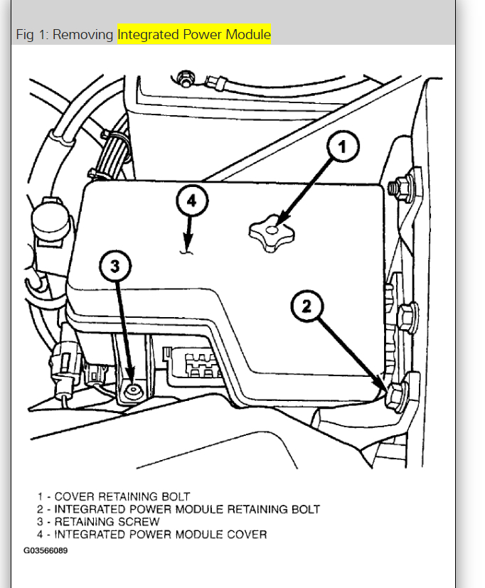
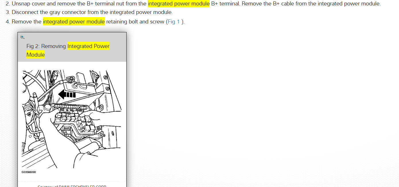
2. Unsnap cover and remove the B+ terminal nut from the integrated power module B+ terminal. Remove the B+ cable from the integrated power module.
3. Disconnect the gray connector from the integrated power module.
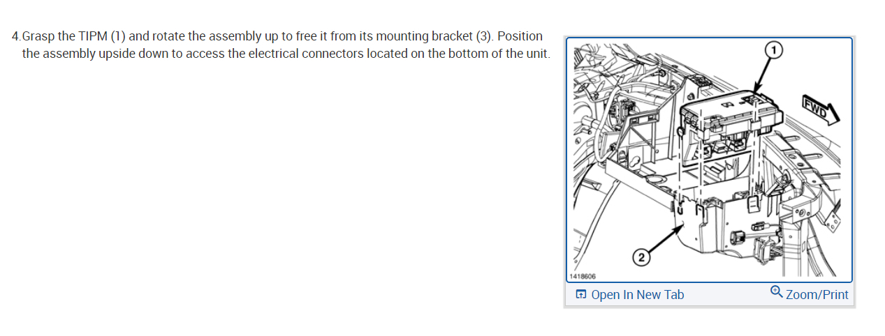
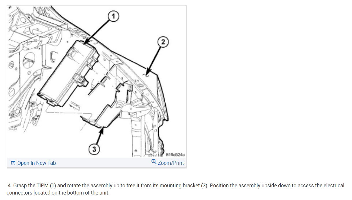
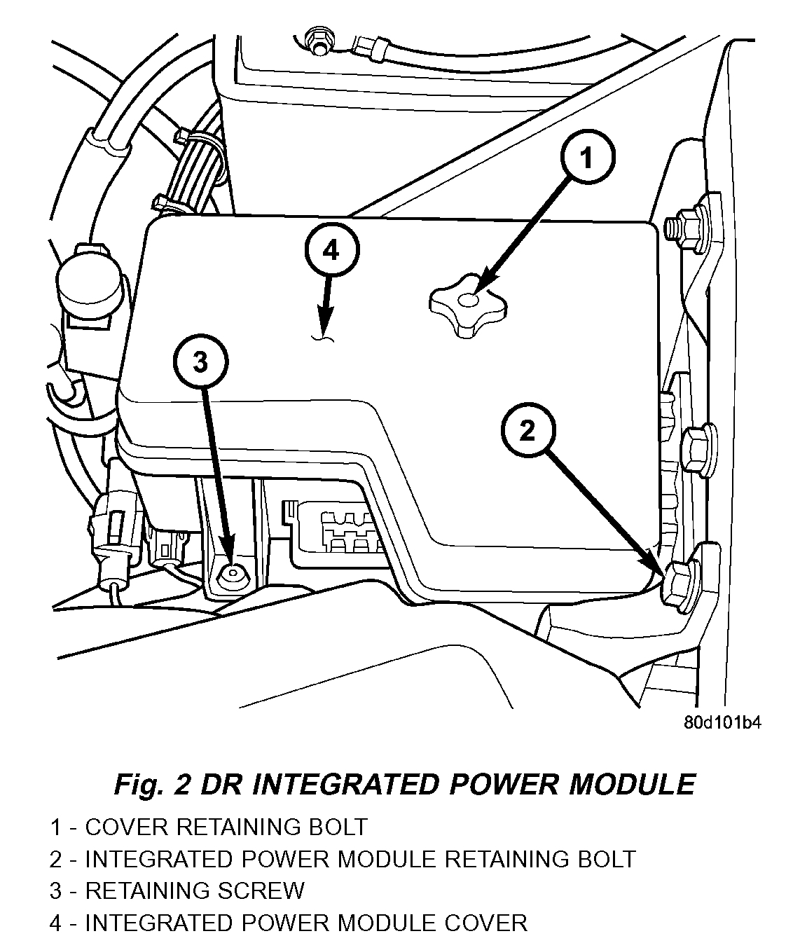
4. Remove the integrated power module retaining bolt and screw (Fig. 2).
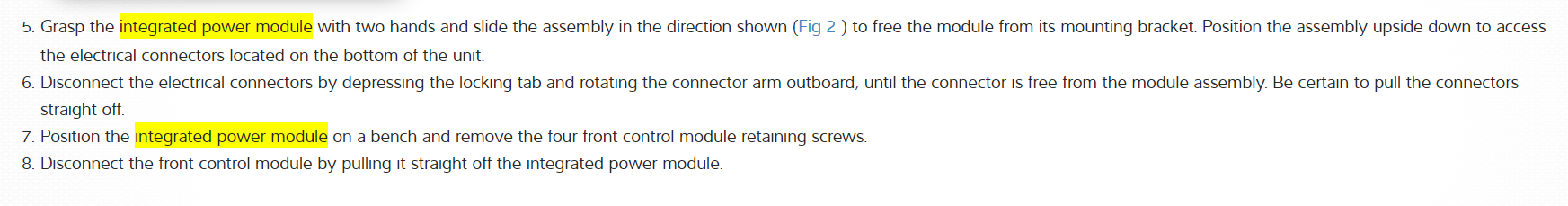
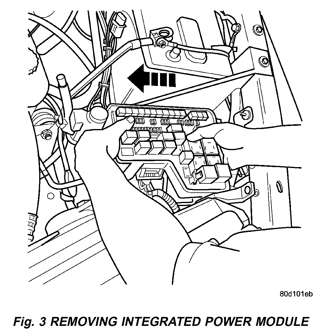
5. Grasp the integrated power module with two hands and slide the assembly in the direction shown (Fig. 3) to free the module from its mounting bracket. Position the assembly upside down to access the electrical connectors located on the bottom of the unit.
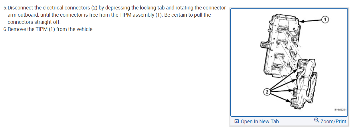
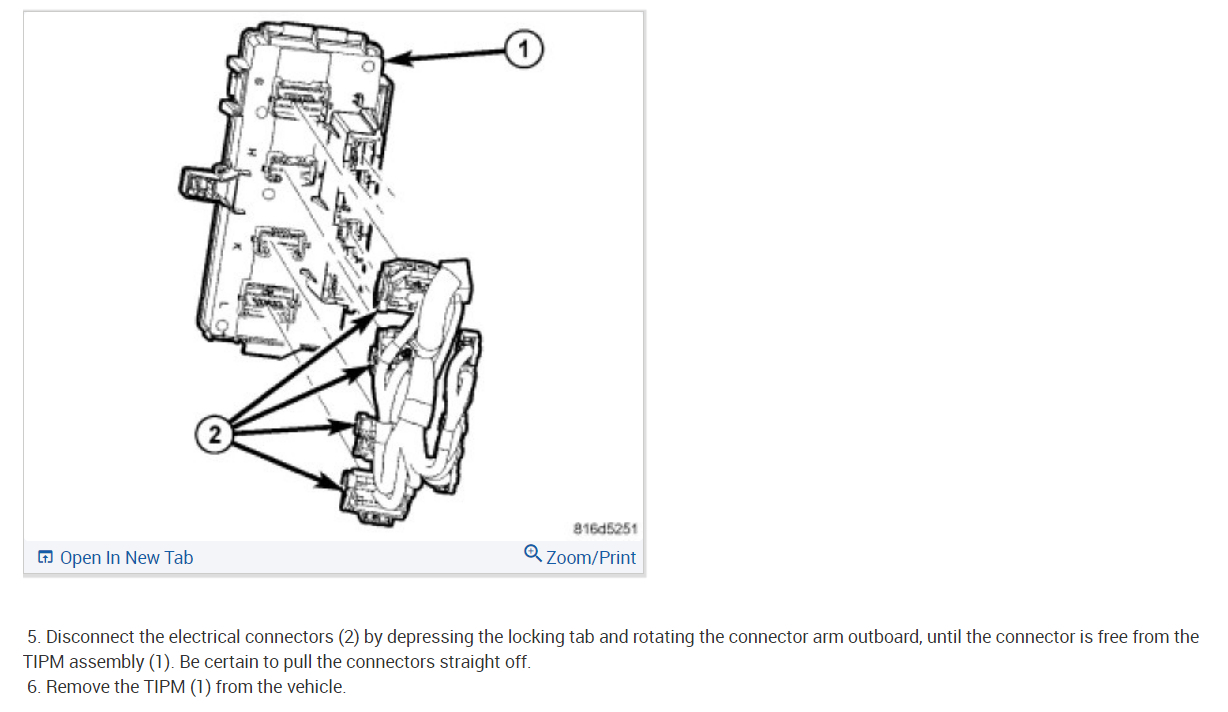
6. Disconnect the electrical connectors by depressing the locking tab and rotating the connector arm outboard, until the connector is free from the module assembly. Be certain to pull the connectors straight off.
7. Position the integrated power module on a bench and remove the four front control module retaining screws.
8. Disconnect the front control module by pulling it straight off the integrated power module.
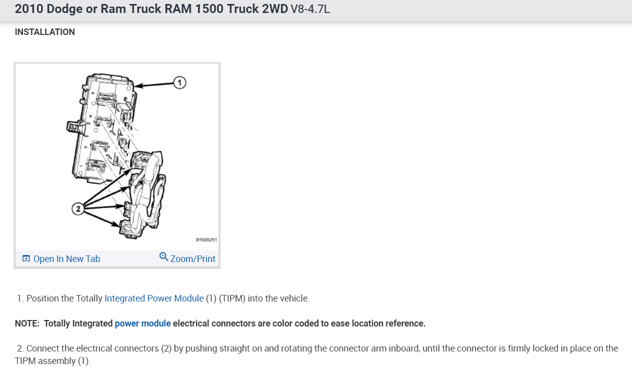
INSTALLATION
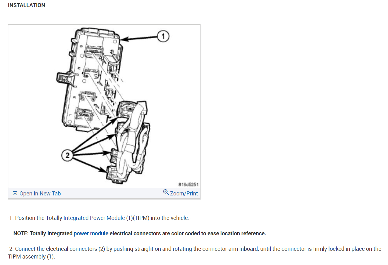
1. Connect the front control module by pushing it straight on the integrated power module electrical receptacle.
2. Install the four front control module retaining screws. Torque to 30 in. Lbs. +/- 5.
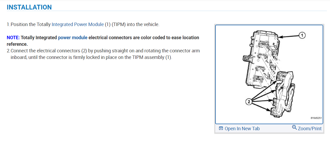
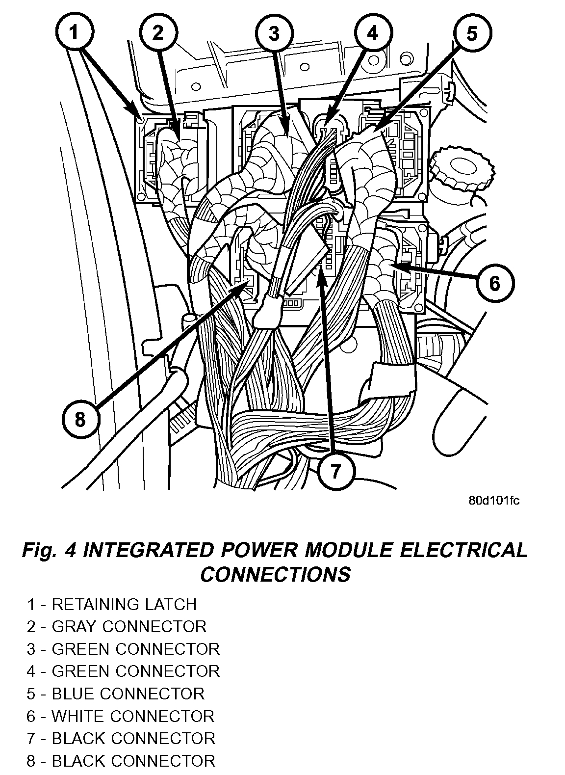
NOTE: Integrated power module electrical connectors are color coded to ease location reference (Fig.4).

3. Connect the electrical connectors by pushing straight on and rotating the connector arm inboard, until the connector is firmly locked in place on the module assembly
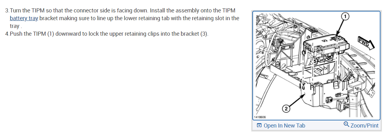
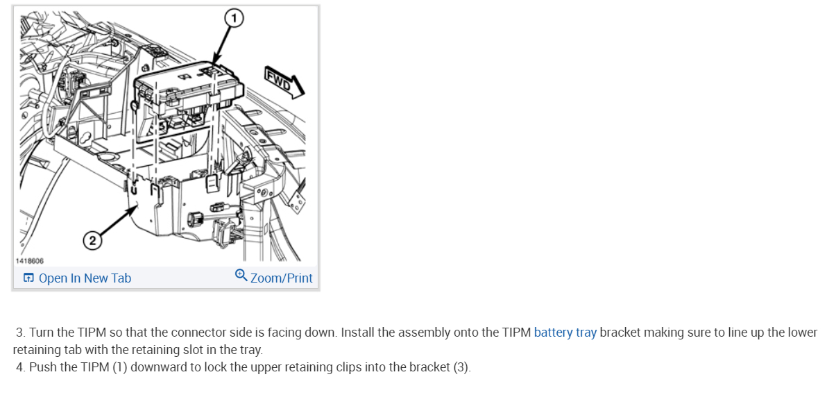
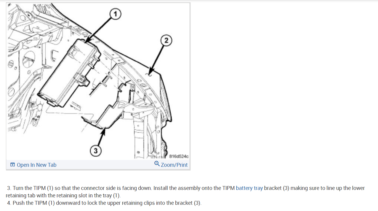
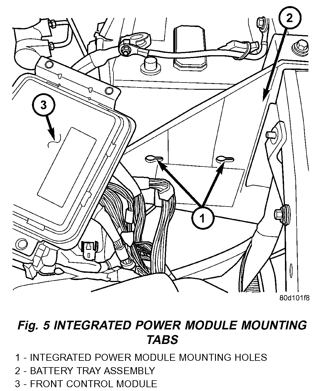
4. Grasp the integrated power module with two hands and install the assembly on the battery tray (Fig. 5).
5. Install the integrated power module retaining bolt and screw.
6. Connect the gray connector on the integrated power module housing.
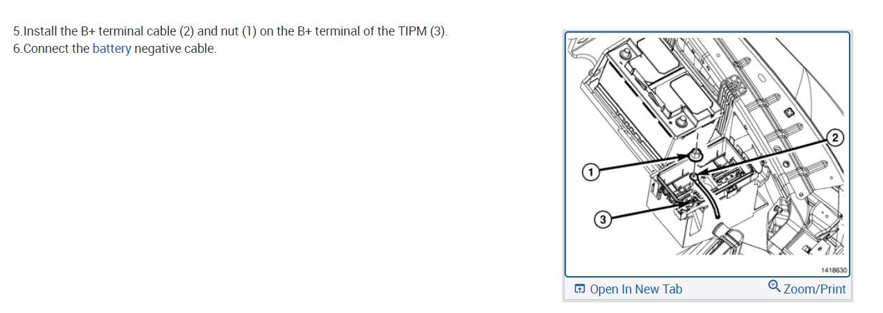
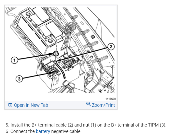
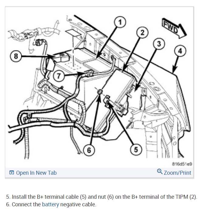
7. Install the B+ terminal cable and nut on the integrated power module B+ terminal. Snap the cover in place
8. Connect the negative and positive battery cables.

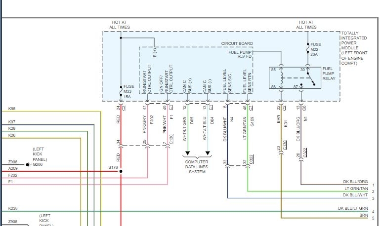
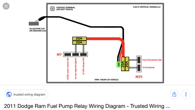
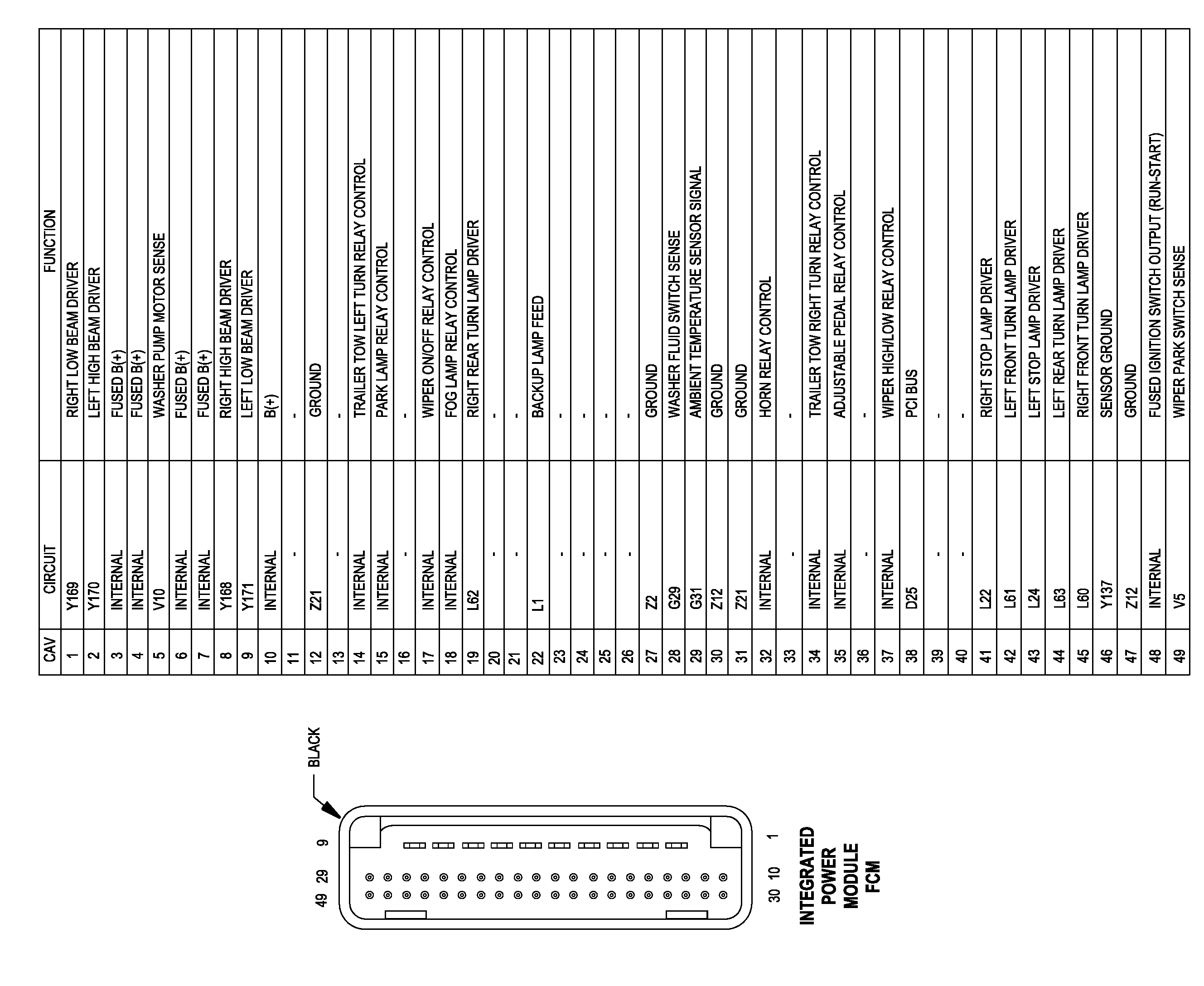
Once it is removed, carefully disconnect the black 49 pin connector, and then inspect pins
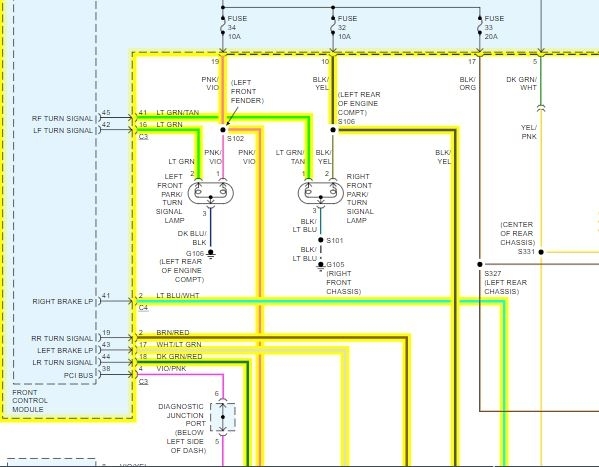
1, 2, 8, 9. If you let me know exactly what is happening, I can narrow the pins down for you. The last picture is the pin I am referring to. Note on the legend, the pins I asked you to check are for the headlights.

If the pins are damaged, they are really not repairable. The entire module needs replaced. It is a plug and play set up, but let me know so I can provide directions.

Let me know what you find or if you have other questions.

Joe
Was this
answer
helpful?
Yes
No
+1
Wednesday, June 23rd, 2021 AT 3:27 PM (Merged)
Tiny
TURTLE1980
  • MEMBER
  • 6 POSTS
Thank you for your response. Well it is both tail lights and both brake lights, however the third brake light on the cab of the truck still works. I even tried to run a wire directly to them off a a toggle switch and the work but when I use my blinkers all the lights tail, brake, tag, and blinker flash at the same time.
Was this
answer
helpful?
Yes
No
Wednesday, June 23rd, 2021 AT 3:27 PM (Merged)

Please login or register to post a reply.

Sponsored links