1996 Dodge Intrepid Gauges have stopped functioning

Tiny
JOEMEY
  • MEMBER
  • 1996 DODGE INTREPID
  • 6 CYL
  • FWD
  • AUTOMATIC
  • 180,000 MILES
I have a 1996 dodge Intrepid. Recently had the windows stop woorking. No power too the fuse. Replaced ingnition switch and now they work. Shortly after that fix the gauges stopped working. Checked all fuses and connections on gauges and BCM.
how can I determine if the gauges are bad or the BCM is bad? Is this a common problem.
Thursday, October 28th, 2010 AT 7:25 PM

3 Replies

Tiny
DAVE H
  • MECHANIC
  • 13,383 POSTS
Hello. Thanks for the donation. Much appreciated

Does the cluster still do the function check @ ignition on?

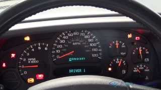
STANDARD INSTRUMENT CLUSTER
Standard instrument cluster is available in 3 types depending on model. All clusters are electro-mechanical type, receiving most of their information from Body Control Module or Timing Control Module via Chrysler Collision Detection (CCD) bus. Instrument cluster consists of speedometer, odometer/trip odometer, tachometer, fuel gauge, temperature gauge and gear selector indicator. Gauges are magnetic air-core type.
When ignition is off, gauge pointers should rest at or below the low graduation. Gauge readings are accurate ONLY when ignition switch is in ON position.
MESSAGE CENTER
Message center module displays various warnings. Module contains a graphic symbol warning light for indicating problem areas on vehicle. Lights include low washer fluid, door and trunk ajar, anti-lock brake, and traction control off or activated (if equipped).
WARNING & INDICATOR LIGHTS
Warning and indicator lights include air bag, brake/parking brake, charging system voltage, cruise, high beam, high temperature, low fuel, low oil pressure, Malfunction Indicator Light (MIL) or check engine light, seat belt and turn signals.
Brake warning indicator will light when parking brake is applied, brake fluid is low in reservoir, hydraulic system fails, ABS indicator light malfunctions or ABS system fails.
TESTING
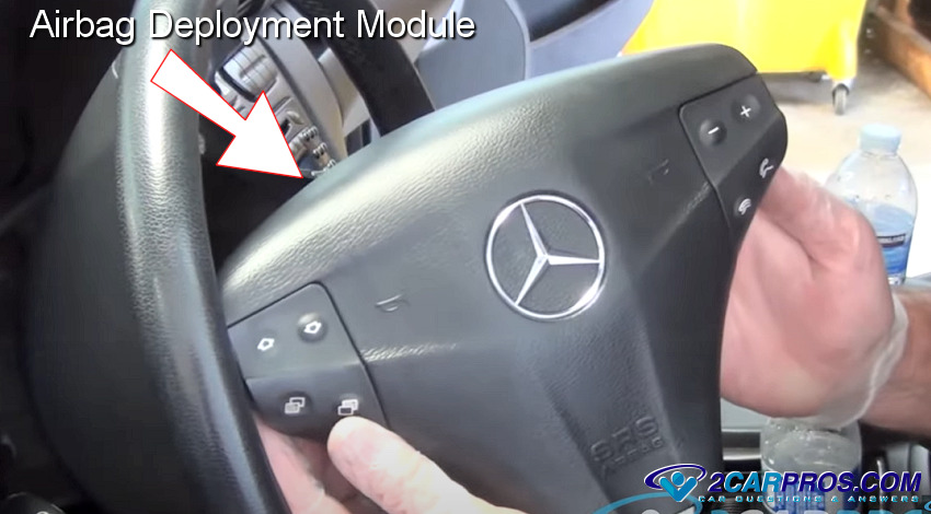
WARNING:Vehicle is equipped with an air bag system. To prevent air bag deployment, disconnect negative battery cable and wait at least 2 minutes before servicing instrument cluster. See appropriate AIR BAG RESTRAINT SYSTEM article.

NOTE:Testing of the instrument panel and gauges requires using a scan tool to check circuits connected to the Body Control Module (BCM). See VEHICLE COMMUNICATIONS article and BODY CONTROL COMPUTER article.

QUICK TEST
As a quick diagnosis, instrument cluster will perform a function check immediately after ignition is switched to RUN/START position. Electronic display, odometer/transmission range indicator and all warning lights EXCEPT low fuel, cruise, high beam, fog lamps and turn signal will light for a brief period.
If cluster is not receiving CCD bus messages, cluster will appear non-functional except for the continuously illuminated air bag indicator, and NO BUS message displayed. If instrument cluster in not receiving CCD bus messages, see appropriate VEHICLE COMMUNICATIONS article.
CAUTION:When battery is disconnected, vehicle computer and memory systems may lose memory data. Driveability problems may exist until computer systems have completed a relearn cycle. See COMPUTER RELEARN PROCEDURES article in GENERAL INFORMATION before disconnecting battery.

WARNING:Disconnect negative battery cable BEFORE servicing instrument panel. When power is required for test purposes, reconnect battery for specific test purpose ONLY. After specific test is completed, disconnect negative battery cable before continuing servicing procedures.
Was this
answer
helpful?
Yes
No
Friday, October 29th, 2010 AT 3:40 AM
Tiny
JOEMEY
  • MEMBER
  • 2 POSTS
Thaks for the reply Dave! Will an autozone test of the system reveal if the CCD bus is operational?

If the bus is not working does that mean I need a new BCM?
Was this
answer
helpful?
Yes
No
Friday, October 29th, 2010 AT 8:19 PM
Tiny
DAVE H
  • MECHANIC
  • 13,383 POSTS
I'm afraid autozone will not be able to do these test's for you. It will need a shop with a good scanner which test's module communication.

Using scan tool, indicate whether vehicle is equipped with specific module. See MODULE APPLICATIONS table under IDENTIFICATION in BODY CONTROL COMPUTER article. Turn ignition off. Disconnect Transmission Control Module (TCM), if equipped. TCM is located at left side of engine compartment, near cowl. Turn ignition on. If scan tool does not display NOT RECEIVING BUS MESSAGES CORRECTLY, replace TCM. If scan tool displays NOT RECEIVING BUS MESSAGES CORRECTLY, go to next step.
Turn ignition off and disconnect Powertrain Control Module (PCM). PCM is located under air cleaner assembly. Turn ignition on. If scan tool does not display NOT RECEIVING BUS MESSAGES CORRECTLY, replace PCM. If scan tool displays NOT RECEIVING BUS MESSAGES CORRECTLY, go to next step.
Turn ignition off and disconnect anti-lock brake controller, if equipped. Controller is located on left fenderwell of engine compartment, behind anti-lock brake pump motor. Turn ignition on. If scan tool does not display NOT RECEIVING BUS MESSAGES CORRECTLY, replace controller. If scan tool displays NOT RECEIVING BUS MESSAGES CORRECTLY, go to next step.
Disconnect overhead travel information system module, if equipped. Turn ignition on. If scan tool does not display NOT RECEIVING BUS MESSAGES CORRECTLY, replace travel module. If scan tool displays NOT RECEIVING BUS MESSAGES CORRECTLY, go to next step.
Turn ignition off and disconnect auto temp control head connector, if equipped. Turn ignition on. If scan tool does not display NOT RECEIVING BUS MESSAGES CORRECTLY, replace auto temp control head. If scan tool displays NOT RECEIVING BUS MESSAGES CORRECTLY, go to next step.
Turn ignition off and disconnect instrument cluster. Turn ignition on. If scan tool does not display NOT RECEIVING BUS MESSAGES CORRECTLY, replace instrument cluster. If scan tool displays NOT RECEIVING BUS MESSAGES CORRECTLY, go to next step.
Disconnect Body Control Module (BCM) connectors. BCM is located behind right kick panel. Turn ignition on. If scan tool does not display NOT RECEIVING BUS MESSAGES CORRECTLY, go to next step. If scan tool displays NOT RECEIVING BUS MESSAGES CORRECTLY, go to next step.
Turn ignition off and wait 5 minutes. Disconnect Air Bag System Control Module (ABSCM) 13-pin connector. ABSCM is located under center of instrument panel. Turn ignition on. If scan tool does not display NOT RECEIVING BUS MESSAGES CORRECTLY, replace ABSCM. If scan tool displays NOT RECEIVING BUS MESSAGES CORRECTLY, replace scan tool cable or scan tool.
Was this
answer
helpful?
Yes
No
Saturday, October 30th, 2010 AT 3:21 AM

Please login or register to post a reply.

Sponsored links