Hello
Well I must say you have a great vehicle there. 210000 miles is great. Obviously things will be going wrong though. It's time. Looks like you have eliminated the fuel question. Relay, filter and pump.
Okay, let's go with spark. When was the last time you changed the plugs and wires? It looks like the routine maintenance for your car is every 30,000 miles you are to change the plugs and every 60,000 miles the wires. I would go with OEM wires to prevent any question on spark jump through the insulation.
There is a Technical Service Bulletin on the plugs that I attached so follow that. Coil info is on that also. You will be referring back to that.
Next I have attached the info on how the ignition system flows. There is an ASD relay. I would test/check that. I have attached that.
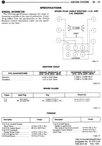
DESCRIPTION
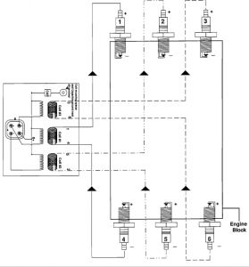
The Distributorless Electronic Ignition System consists of a Powertrain Control Module (PCM), camshaft position sensor, crankshaft position (CKP) sensor, and an ignition coil pack containing three individual coils.
OPERATION
The PCM controls ignition timing and coil dwell by controlling the ground paths to each coil. It has the capability of igniting the fuel mixture according to different engine operating conditions by delivering a variable electronic spark advance curve.
The PCM has a built in microprocessor that continually receives input from the engine sensors. The PCM then electronically advances or retards the ignition timing to provide good driveability during all operating conditions.
When the engine is cold the PCM will provide a set amount of advanced timing to assure a quick efficient start.
When the engine is warm the amount of spark advance provided by the PCM is determined by three input factors, coolant temperature, engine rpm, and manifold pressure.
The PCM also receives information from the oxygen sensor and adjusts the air-fuel mixture to assure the most efficient fuel burn possible.
The PCM also controls the Auto Shut-Down (ASD) Relay, which provides power to the ignition coil, fuel pump, oxygen sensor heater element, and fuel injectors.
The Auto Shutdown (ASD) relay is located inside the power distribution center. The power distribution center is located next to the battery.
NOTE: Relay terminal numbers can be found on the bottom of the relay:
TERMINAL IDENTIFICATION
Terminal number 30 is connected to battery voltage and can be switched or B + (hot) at all times.
Terminal number 87A is connected (a circuit is formed) to terminal 30 in the de-energized (normally OFF) position.
Terminal number 87 is connected (a circuit is formed) to terminal 30 in the energized (ON) position. Terminal number 87 then supplies battery voltage to the components being operated.
Terminal number 86 is connected to a switched (B+) power source (ignition in ON or RUN).
Terminal number 85 is grounded by the PCM.
PROCEDURE
Remove relay before testing.
Using an ohmmeter, perform a resistance test between terminals 85 and 86. Resistance value (ohms) should be 75 ±5 ohms for resistor equipped relays.
Connect the ohmmeter between terminals number 87A and 30. Continuity should be present at this time.
Connect the ohmmeter between terminals number 87 and 30. Continuity should not be present at this time.
Use a set of jumper wires (16 gauge or smaller). Connect one jumper wire between terminal number 85 (on the relay) to the ground side (-) of a 12 Volt power source.
Attach the other jumper wire to the positive side (+) of a 12V power source. Do not connect this jumper wire to relay at this time. CAUTION: Do not allow the ohmmeter to contact terminals 85 or 86 during these tests. Damage to ohmmeter may result.
Attach the other jumper wire (12V +) to terminal number 86. This will activate the relay. Continuity should now be present between terminals number 87 and 30. Continuity should not be present between terminals number 87A and 30.
Disconnect jumper wires from relay and 12 Volt power source.
If continuity or resistance tests did not pass, replace relay.
Next are the coils. I have attached the checks for those.
The ignition coil pack is mounted on the right cylinder head.
NOTE: Coil 1 fires cylinders 1 and 4, coil 2 fires cylinders 2 and 5, and coil 3 fires cylinders 3 and 6. Each coil tower is labeled with the number of the corresponding cylinder.
Disconnect the electrical connector from the coil pack.
Measure the primary resistance of each coil. At the coil, connect an ohmmeter between the B+ pin and the pin corresponding to the cylinders in question (Fig. 18).
Resistance on the primary side of each coil should be 0.45 - 0.65 ohm at 21 °to 27 °C (70 °to 80 °F) .
A coil that has not been allowed to cool off, would result in inaccurate measurement results.
Replace the coil if resistance is not within tolerance.
Remove ignition cables from the secondary towers of the coil. Measure the secondary resistance of the coil between the towers of each individual coil (Fig 19).
Secondary resistance should be 7,000 to 15,800 ohms .
Replace the coil if resistance is not within tolerance.
My suggestion is start with replacing the plugs and wires first. Drive it and see how it does.
Next check the ASD. Test and then drive it and see how it does.
Next the coils. Test the drive it and see how it does. Even if they test good, really look them over for any leaks, damage or anything that isn't right.
I would not be surprised with the number of miles you have on your vehicle if one or all need replacing. You have a great vehicle there...........let us know how that does.
Oct 22, 2008 at 11:16 PM