Here are diagnostic procedures fr the code.
DTC P1787: OD HYDRAULIC PRESSURE SWITCH CIRCUIT
Circuit Description
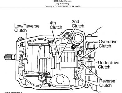
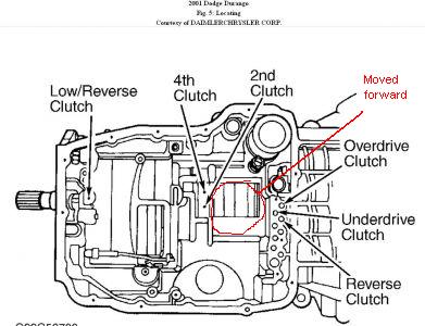
After a shift into a forward gear and with engine speed greater than 1000 RPM, the TCM momentarily turns on element pressure to clutch circuits that don't have pressure to confirm the correct pressure switch closes. If pressure switch does not close 2 times, DTC P1787 will set.
Possible Cause
The following items may be area of concern:
"� Open in transmission relay output circuit.
"� Other line pressure-related DTCs present.
"� Excessive debris in oil pan.
"� Intermittent wiring and connector problems.
"� Internal transmission problem (OD pressure test).
"� Other speed ratio and/or pressure switch DTCs present.
"� OD pressure switch sense circuit shorted to voltage, shorted to ground or open.
"� Faulty line pressure sensor.
"� Poor line pressure sensor connection.
"� 5-volt supply circuit open or shorted to ground.
"� Faulty TCM.
"� Incorrect fluid level.
Diagnostic Procedure
1. Using scan tool, check for line pressure-related DTCs. If DTCs P1720, P1721, P1722, P1724 or P1791 are present, diagnose using appropriate test. If line pressure-related DTCs are not present, go to next step.
NOTE:
Consult manufacturer's warranty documentation (if applicable) prior to performing repairs. Replace transmission or solenoid/TRS assembly as required by current warranty policy.
2. Using scan tool, check for transmission-related DTCs P0733 and/or P1781. If any of these DTCs are present, replace solenoid/TRS assembly. If DTCs P0733 and/or P1781 are not present, go to next step.
3. Start engine. Warm transmission to at least 180 °F (82 °C). Apply brakes. While monitoring line pressure with scan tool, move gearshift lever through each gear position and record line pressure reading. Allow line pressure to stabilize for at least 5 seconds in each gear. If pressure remains steady at 85-95 psi (6.0-6.7 kg/cm
2 ) through entire procedure, go to next step. If pressure did not remain steady as specified, turn engine off and go to step 10.
4. Turn ignition on. While monitoring actual line pressure with scan tool, firmly push line pressure sensor harness connector toward transmission. If actual line pressure changes to about 30 psi (2.1 kg/cm 2 ), repair poor connection at line pressure sensor. If actual line pressure does not change, go to next step.
NOTE:
When comparing line pressure voltage readings with
transmission simulator and scan tool, voltage readings should be within.25 volt of each other.
5. Turn ignition switch to LOCK position. Remove starter relay from Power Distribution Center (PDC). Install Transmission Simulator (8333). Turn ignition on. While monitoring line pressure sensor voltage on scan tool, turn rotary knob on transmission simulator to all 3 line pressure positions. If line pressure sensor voltage remains steady while changing simulator knob position, go to next step. If line pressure sensor voltage does not remain steady while changing simulator knob position, go to step 9.
6. Turn ignition switch to LOCK position. Disconnect TCM and line pressure sensor harness connectors. Measure resistance of 5-volt supply circuit between TCM harness connector terminal No. 38 and line pressure sensor harness connector terminal No. 2. If resistance is greater than 5 ohms, repair open circuit. If resistance is 5 ohms or less, go to next step.
7. Measure resistance between ground and 5-volt supply circuit at TCM harness connector terminal No. 38. If resistance is less than 5 ohms, repair circuit for short to ground. If resistance is 5 ohms or greater, go to next step.
8. If no other potential causes for DTC P1787 remain, TCM is assumed to be faulty. Repair or replace as necessary.
9. The TCM and wiring are functioning properly. Replace line pressure sensor.
10. Ensure all harness connectors, wiring, oil cooler connections and fluid level are okay. Repair as necessary. Using scan tool, check STARTS SINCE SET counter. If counter displays 2 or less, go to next step. If counter does not display 2 or less, go to step 20.
11. Turn ignition switch to LOCK position. Remove starter relay from Power Distribution Center (PDC). Install Transmission Simulator (8333). Turn ignition on. Place pressure switch selector on OD. Monitor scan tool display while pressing switch test button and wiggling wire harness to TCM. If OD pressure switch state changes to CLOSED and remains closed while wiggling wire harness, go to next step. If operation was not as
specified, go to step 15.
NOTE:
Ensure transmission fluid is at normal operating temperature. Check and adjust fluid level as necessary. Fluid level may not show on dipstick if transmission temperature is less than 50 °F (100 °C), even though transmission has an adequate fluid level.
12. Ensure transmission is at normal operating temperature. Check fluid level. Fill as necessary and retest. If fluid level is okay, go to next step.
13. Remove transmission oil pan and inspect for excessive debris or contamination. Repair as necessary. If no debris is found, go to next step.
14. Transmission has an internal problem and must be replaced or repaired. If repairing transmission, ensure to inspect valve body and replace or repair as necessary. If valve body is okay, replace solenoid/TRS assembly.
15. Turn ignition switch to LOCK position. Disconnect TCM and solenoid/TRS assembly harness connectors. Measure resistance of OD pressure switch sense circuit between TCM harness connector terminal No. 9 and solenoid/TRS assembly harness connector terminal
No. 16. If resistance is greater than 5 ohms, repair open circuit. If resistance is 5 ohms or less, go to next step.
16. Measure resistance between ground and OD pressure switch sense circuit at TCM harness connector terminal No. 9. If resistance is less than 5 ohms, repair circuit for short to ground. If resistance is 5 ohms or greater, go to next step.
NOTE:
When testing output circuit with a test light, ensure test light illuminates brightly. Compare test light brightness of circuit to brightness of test light when connected to direct battery voltage. If circuit does not illuminate with same brightness as direct battery voltage, circuit must be repaired.
17. Connect test light between ground and transmission control relay output circuit at solenoid/TRS assembly harness connector terminal No. 10. Turn ignition on. If test light illuminates brightly, remove test light and go to next step. If test light does not illuminate brightly, repair open or high resistance in transmission control relay output circuit.
18. Turn ignition switch to LOCK position. Remove transmission control relay from Power Distribution Center (PDC). Using fused jumper wire, jumper fused B+ circuit (terminal No. 30) and transmission control relay output circuit (terminal No. 87) together at transmission control relay connector. Turn ignition on. Measure voltage between ground and OD pressure switch sense circuit at TCM harness connector terminal No. 9. If voltage is greater than one volt, repair circuit for short to voltage. If voltage is one volt or less, go to next step.
19. If no other potential causes for DTC P1787 remain, TCM is assumed to be faulty. Repair or replace as necessary.
20. Conditions necessary to set DTC are not present at this time. Using appropriate wiring diagram as a guide, inspect wiring and connectors associated with circuits in question. Wiggle wires while checking for shorted and open circuits. Repair as necessary. If circuits are okay, testing is complete.
Saturday, September 4th, 2010 AT 1:24 PM