1989 Chevy Truck low volts

Tiny
DAPACJ
  • MEMBER
  • 1989 CHEVROLET TRUCK
Electrical problem
1989 Chevy Truck V8 Four Wheel Drive Automatic

I recently posted a question about my charging system problem and have yet to hear any response. The alt is new, grounds and fuses checked out good. Voltage regulator isn't engaging when truck is running. The old alt tested 14.5v but had bearing issues, while on the truck the old one only showed 12v. It was tested by advanced auto after changing alt didn't fix the problem. There is no power coming off harness for the alt(brown wire). Gauge in the dash reads the same as multimeter when truck is running(12.16v), with the truck off battery reads 12.5v and I don't have starting problems just charging. What am I overlooking?I need my truck up and running to get to my doctors appt. Everyone I talk to can't figure it out. Hope to hear from someone soon.
Wednesday, February 24th, 2010 AT 12:25 PM

7 Replies

Tiny
MERLIN2021
  • MECHANIC
  • 17,250 POSTS
2. If an undercharging condition is suspected, disconnect 4-wire connector from alternator. Turn ignition on with engine off. Connect a voltmeter between terminal "L" in wiring harness and ground. Record reading. 3. If terminal "I" is used, connect voltmeter between terminal "I" and ground. Record reading. If voltmeter reads battery voltage, circuits are okay. If voltmeter reads zero, this indicates an open circuit between terminal checked and battery. Repair as necessary. Alternator Output Test 1. Connect an ammeter in circuit at "BAT" terminal of alternator. Turn on all available accessories. Connect a carbon pile across battery. Operate engine at 2000 RPM and adjust carbon pile as required to obtain maximum current output while maintaining 13 volts or more. 2. Ampere output must be within 15 amps of rated output. See the CS SERIES ALTERNATOR OUTPUT SPECIFICATIONS. If output is not within 15 amps of rated output, replace alternator. SI SERIES Overcharged or Undercharged Battery 1. If an overcharging condition is suspected, attach a voltmeter across battery terminals. Run engine at a moderate speed with all accessories off. If voltmeter reads 15.5 volts or more, remove alternator for repair. 2. If an undercharging condition is suspected, turn ignition on. Connect a voltmeter from alternator "BAT" terminal to ground. Voltmeter should read 12 volts. Connect voltmeter between No. 1 terminal and ground. Voltmeter should read one volt or more. 3. Connect voltmeter between No. 2 terminal and ground. Voltmeter should read 12 volts. A zero reading on any connection indicates an open between connection and battery. Opens in the No. 2 lead may be between terminals at the crimp between harness wire and terminal, or in wire. Alternator Output Test 1. Connect an ammeter in circuit at "BAT" terminal of alternator. Turn on all available accessories. Connect a carbon pile across battery. Operate engine at 2000 RPM and adjust carbon pile as required to obtain maximum current output. 2. Ampere output must be within 10 amps of rated output. See the SI SERIES ALTERNATOR OUTPUT SPECIFICATIONS. If output is not within 10 amps of rated output, ground field winding by inserting a screwdriver into test hole. Repeat step 1). 3. If output increases to within 10 amps of rated output with field grounded, regulator is defective. If output remains below 10 amps of rated output, check field winding, diode trio, rectifier bridge, and stator. NOTE: Tab is within 3/4" of casting surface. DO NOT force tool beyond 1" into end frame. If test hole is not accessible, proceed to BENCH TESTING. Page 1 of 1 2/24/2010 .
Check your email for the diagram of the alternator types and wire ID's.
Was this
answer
helpful?
Yes
No
-1
Wednesday, February 24th, 2010 AT 1:19 PM
Tiny
DAPACJ
  • MEMBER
  • 8 POSTS
Merlin2021, I read your email about testing the alt. Had it tested14.5v on the bench. There are no volts present off the plis plug on the alt. Power going to alt is12.5v. Blue fusible link has 12.5 volts on both sides. My truck uses the I on alt and there is no volts at any of the prongs on alt. What could be stuck in an open position?When key is first turned on(w/o starting) the volt gauge will jump up to almost 14vollts, but drops the second truck starts
Was this
answer
helpful?
Yes
No
Wednesday, February 24th, 2010 AT 7:09 PM
Tiny
MERLIN2021
  • MECHANIC
  • 17,250 POSTS
With all wires connected, take a reading at the battery, with everything off, then turn heat, wipers radio on, and take a reading, increase rpm's to 2000 and take a reading, post results.
https://www.2carpros.com/how_to/how_to_test_alternator.htm
Was this
answer
helpful?
Yes
No
Thursday, February 25th, 2010 AT 2:21 AM
Tiny
DAPACJ
  • MEMBER
  • 8 POSTS
After checking the alt. Plug in and hooking harness back up I started the truck and truck is now running at 14.75v-14.9v. With the truck off battery volts are 12.53. The truck has never ran with that many volts showing on the gauge(almost at 16v mark, but multimeter says 14.75-14.9v.I am hoping this doesn't turn into an overcharging issue. I think the cause of this is in the pig tail off the alt. The wiggle test was the only one not performed. If this continues I will be in contact. Thanks for the help.
Was this
answer
helpful?
Yes
No
+1
Thursday, February 25th, 2010 AT 5:08 PM
Tiny
MERLIN2021
  • MECHANIC
  • 17,250 POSTS
14-15 volts is acceptable, your dash mounted gauge is probably not calibrated, and wont harm the battery.
Was this
answer
helpful?
Yes
No
Thursday, February 25th, 2010 AT 5:46 PM
Tiny
DAPACJ
  • MEMBER
  • 8 POSTS
My nephew has a 92 lumina w/3.1l that has been burning up f/p relays. He put it in a shop to have a no start checked out. I had already told him it was the crank sensor(and it was), after the shop fixed that and their oil leak(they dropped oil pan to remove sensor). While running the car for 30 minutes they ran it out of gas, so they put fuel in it and let him have his car back. Now when he starts the car it shuts down a second later. The ignition module was changed when they were working on no start, has a new fuel sending unit and f/p relay has been changed atleast 3 times that I know of.I used to do all the mechanical work in the family until my disability happened, so now we have to trust other people. So far your site is more helpful than shops in our area. If you have any ideas for him to check let me know and I will pass on your knowledge to him. Hope to hear from you soon
Was this
answer
helpful?
Yes
No
Sunday, February 28th, 2010 AT 11:31 AM
Tiny
MERLIN2021
  • MECHANIC
  • 17,250 POSTS
If the fuel system was OK before the trip to last chance gagage, I would test the ground and power wiers to the tank unit. They may have pinched, in my opinion the ground wire...crossed to power? Check the PCM and Fuel pump grounds as in this diagram.


https://www.2carpros.com/forum/automotive_pictures/62217_fp_2.jpg


Fuel Pump Relay (A-5)

Fuel Pump Relay By-Pass Procedure

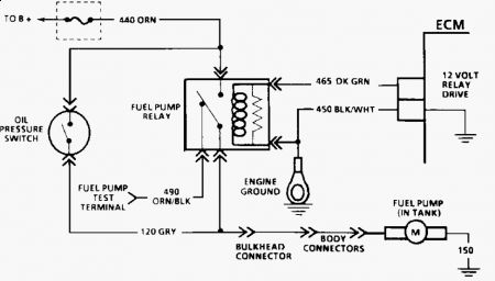
Fig. 4: Typical Fuel Pump Relay Schematic Courtesy of GENERAL MOTORS CORP.

Oil Pressure Switch Fuel Pump Back-Up

With engine idling, disconnect fuel pump relay. Engine should continue to run through oil pressure switch back-up circuit. If engine stalls, check oil pressure switch and related wiring.

Page 1 of 1
1.Disconnect fuel pump relay connector. Refer to COMPONENT LOCATIONS at the end of this article to locate fuel pump relay. Apply battery voltage and ground to fuel pump relay winding terminals. To identify fuel pump relay terminals, see appropriate wiring diagram at the end of this article. 2.Using an ohmmeter, check for continuity between fuel pump relay power supply terminal and fuel pump drive terminal. Continuity should exist ONLY with relay energized. If relay does not test as indicated, replace relay. 3.To by-pass fuel pump relay (to test fuel pump and wiring when fuel pump is not energizing), see FUEL PUMP RELAY BY-PASS PROCEDURE below.
1.If fuel pump will not energize, relay may be by-passed to test fuel pump and related wiring. See Fig. 4 . Turn ignition off. Disconnect fuel pump relay connector. Using a fused jumper wire, apply battery voltage to fuel pump test connector (located in engine compartment). For fuel pump test connector location, refer to COMPONENT LOCATIONS at end of this article. See Fig. 53 - Fig. 55 . 2.If fuel pump runs and relay tests okay, check for faulty connections at relay. If fuel pump does not run, check for faulty wiring between relay and fuel pump or replace defective fuel pump.
Also test injectors, with an ohm meter, test warm, reading should be 12.0-12.4 ohms, Replace ANY NOT IN SPEC, MOST TECHS RECOMMEND CHANGING ALL AT THE SAME TIME..
Was this
answer
helpful?
Yes
No
Sunday, February 28th, 2010 AT 3:59 PM

Please login or register to post a reply.

Sponsored links