Steering column coupling bolts5541-
Steering column dash seal nuts (late build only)8-71
Steering column mounting bolts2821-
Steering column opening panel bolts8-71
Steering column through bolt2518-
Steering wheel bolt
first numbers are Nm second set is ft.lb
1. Remove the steering column opening trim.
2. Using a suitable cutting tool, carefully cut through the 2 cutoff lines and discard the instrument panel cutoff panel.
3. Remove the 4 screws and the steering column opening panel.
^ To install, tighten to 8 Nm (71 lb-in).
4. Remove the LH instrument panel side finish panel.
5. Through the side finish panel opening, remove the ground wire eyelet bolt.
^ Position the 2 ground wire eyelets and wires aside.
6. Through the side finish panel opening, disconnect the 2 instrument panel wiring harness electrical connectors and, if equipped, the battery high-voltage jumper switch electrical connector.
^ Position the harnesses and connectors aside.
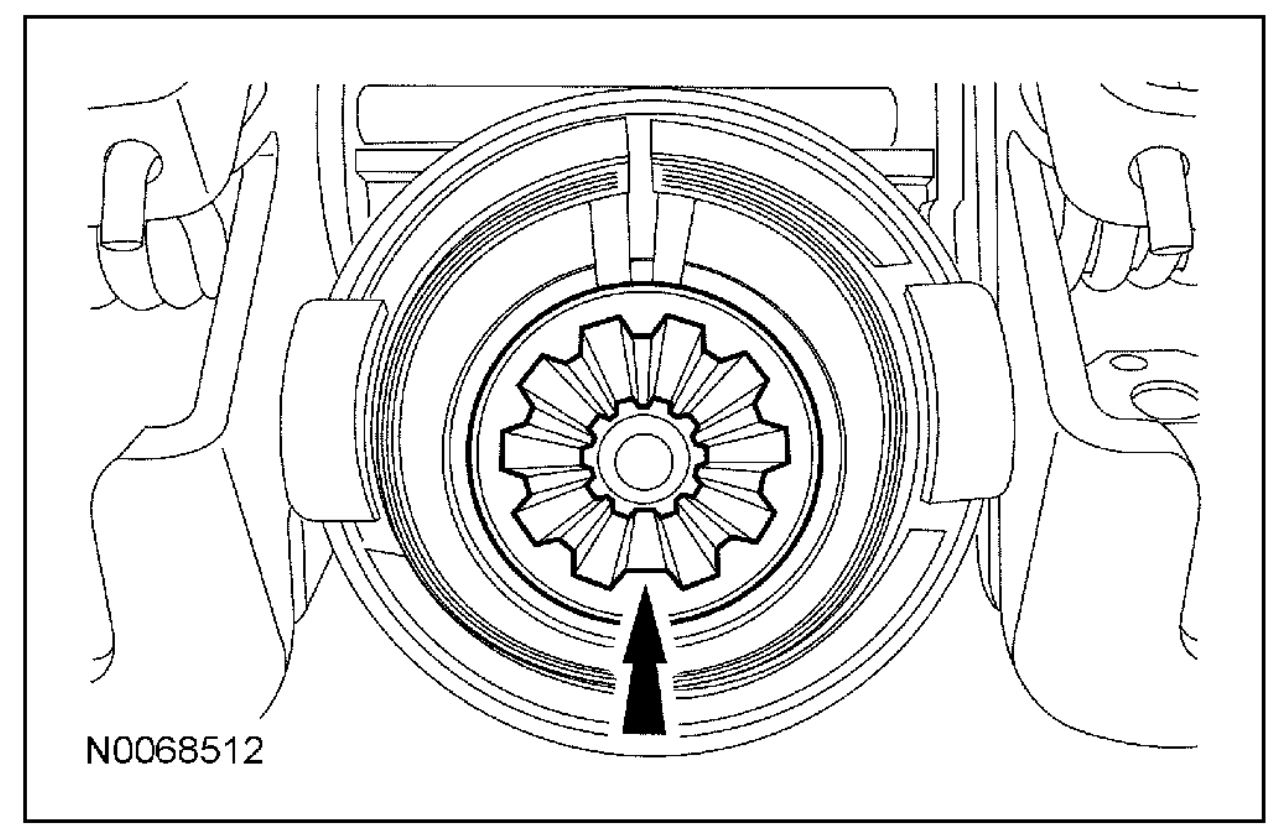
7. Turn the ignition switch to the ON position and rotate the steering wheel clockwise until the steering column coupling-to- steering column bolt is accessible.
8. Through the side finish panel opening, remove and discard the steering column coupling-to-steering column bolt.
^ To install, tighten to 55 Nm (41 lb-ft).
9. Remove the clockspring.
10. Disconnect the following electrical connectors:
^ Multi-function switch
^ Ignition switch
^ Passive anti-theft system (PATS) transceiver (if equipped)
^ Headlamp switch
^ Headlamp dimmer adjuster
^ Message center (if equipped)
^ Electronic power assist steering (EPAS) 6-pin
^ EPAS 2-pin
11. Detach the 2 electrical harness pin-type retainers from the steering column.
12. Detach the data link connector (DLC) from the DLC mounting bracket.
13. Position all electrical harnesses and connectors aside.
14. Detach the steering column coupling from the steering column.
15. CAUTION: Do not remove the steering column through bolt at this time or damage to the steering column can occur.
Loosen the steering column through bolt.
16. CAUTION: Support the upper end of the steering column while removing the 2 steering column mounting bolts or damage to the steering column can occur.
Remove the 2 steering column mounting bolts.
^ To install, tighten to 28 Nm (21 lb-ft).
17. CAUTION: Do not release the tilting mechanism while lowering the steering column or damage to the steering column can occur.
Carefully lower the upper end of the steering column to the floor of the vehicle.
18. CAUTION: Support the lower end of the steering column while removing the through bolt or damage to the steering column can occur.
Remove the steering column through bolt and carefully remove the steering column through the steering column opening.
^ To install, tighten to 25 Nm (18 lb-ft).
19. CAUTION: Do not allow the steering column upper and lower halves to become separated. If the column halves become separated, make sure that the upper and lower column shaft master (larger) splines are correctly aligned. Once the splines are correctly aligned, the column halves will slide together easily using hands only. Do not force the upper and lower column halves together or damage to the column may occur.
20. NOTE: When a new steering column is installed the EPAS module in the steering column assembly must be reconfigured.
Reconfigure the EPAS module. For additional information refer to Information Bus for Programmable Module Installation.
21. NOTE: When a new steering column is installed, the steering column position sensor must be calibrated.
Calibrate the steering wheel position sensor. For additional information, refer to Steering Wheel Position Sensor Calibration in Diagnosis and Testing. See: Steering Angle Sensor > Programming and Relearning > Steering Wheel Position Sensor Calibration
Steering Wheel Position Sensor Calibration
1. Place the vehicle on a flat level surface with the transmission in PARK.
2. Place the steering wheel in the straight ahead position and remove hands from the wheel.
3. Connect the scan tool to the vehicle.
4. Turn the ignition key to the RUN position.
5. Using the scan tool, select the steering position sensor calibration and follow the scan tool instructions.
6. Clear any power steering control module DTCs.
7. NOTE: After turning the ignition key to the OFF position, wait at least 25 seconds before carrying out any procedures that require the battery to be disconnected or module memory loss may occur.
Turn the ignition key to the OFF position.
8. Road test the vehicle. If the steering wheel is not in the straight ahead position while driving on a flat road surface, check and adjust the alignment as necessary.
Feb 16, 2014 at 1:32 PM