Here are the procedures for replacing the hub.
FRONT HUB UNIT BEARING
REMOVAL
1. Disconnect the ground cable from the battery.
2. Lift-up the vehicle, and remove the front wheels.
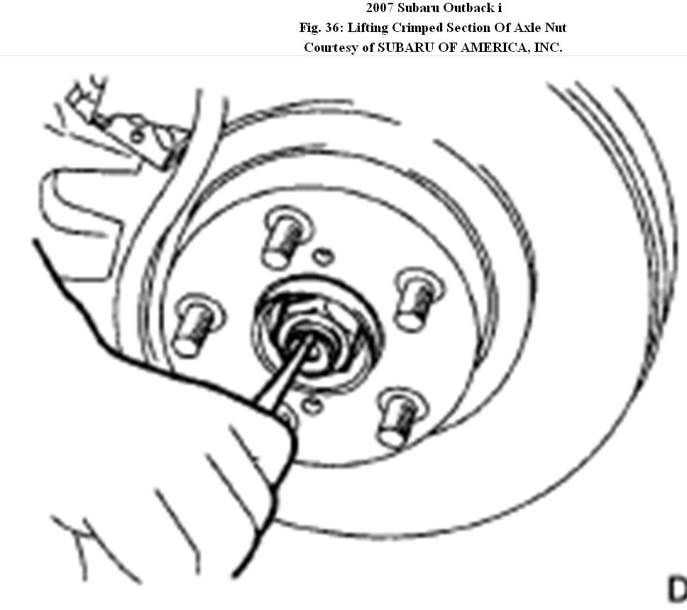
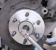
3. Lift the crimped section of axle nut.
Fig. 36: Lifting Crimped Section Of Axle Nut
4. Remove the axle nut using a socket wrench while depressing the brake pedal.
CAUTION:Remove the wheel before loosening the axle nut. Failure to
follow this rule may damage the wheel bearings.
5. Remove the disc brake caliper from the housing, and suspend it from strut using a wire.
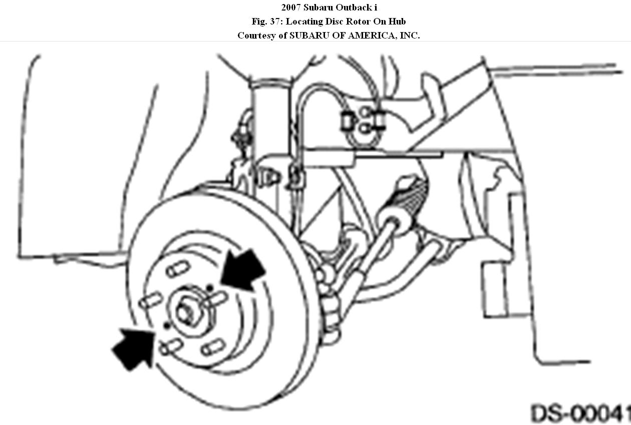
6. Remove the disc rotor from the hub.
NOTE:
If it is difficult to remove the disc rotor from the hub, drive the 8 mm bolt into the threaded end of rotor, and then remove the rotor.
Fig. 37: Locating Disc Rotor On Hub
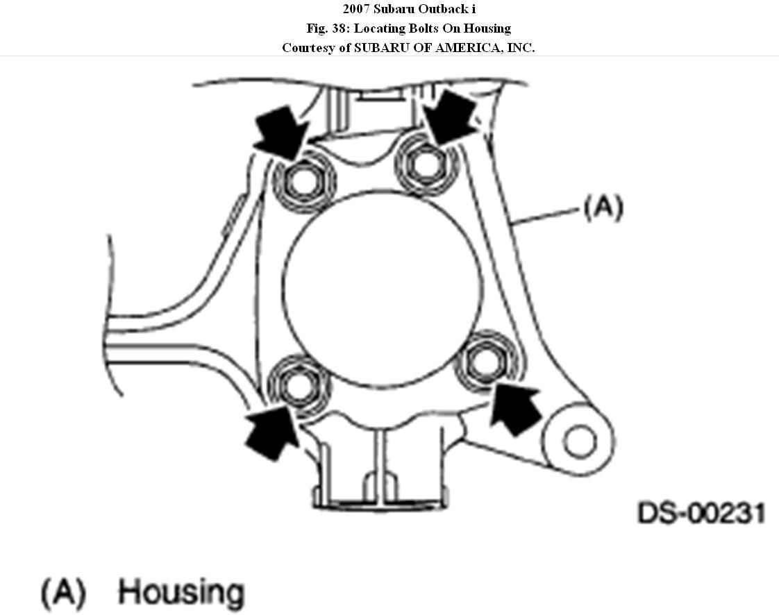
7. Remove the four bolts from the housing.
Fig. 38: Locating Bolts On Housing
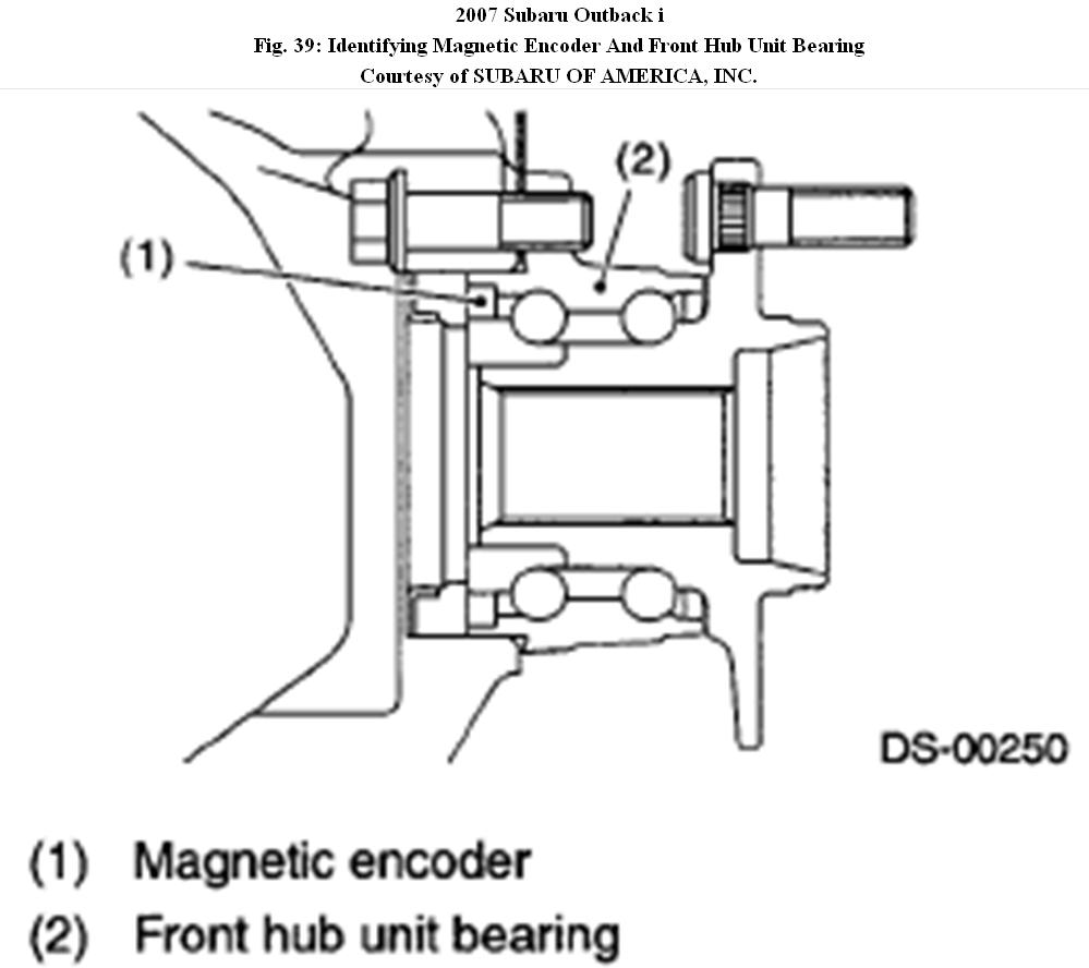
CAUTION:
� Do not get closer the tool which charged magnetism to magnetic encoder.
� Be careful not to damage the magnetic encoder.
Fig. 39: Identifying Magnetic Encoder And Front Hub Unit
Bearing
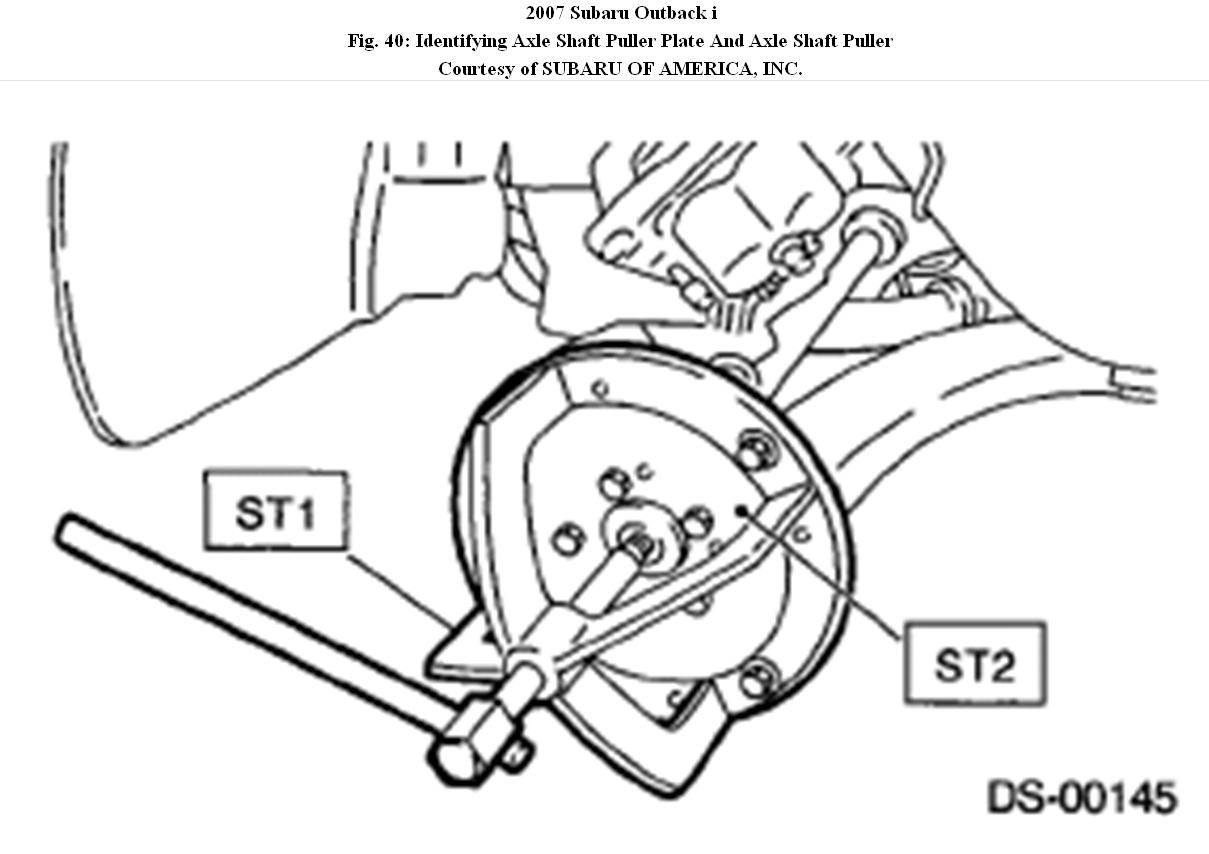
8. Remove the front hub unit bearing. If it is hard to remove, use the ST.
ST1 926470000 AXLE SHAFT PULLER
ST2 28099PA110 AXLE SHAFT PULLER PLATE
Fig. 40: Identifying Axle Shaft Puller Plate And Axle Shaft Puller
INSTALLATION
1. Place the disc cover between housing and front hub unit, and tighten the four bolts.
Tightening torque: 65 N.M (6.6 kgf-m, 47.9 ft-lb)
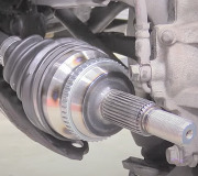
2. Install the front drive shaft.
3. Tighten the axle nut temporarily.
4. Install the disc rotor to hub.
5. Install the disc brake caliper on the housing.
Tightening torque: 80 N.M (8.2kgf-m, 59 ft-lb)
6. While depressing the brake pedal, tighten a new axle nut (olive color) to the specified torque and lock it securely.
Tightening torque: 220 N.M (22.4 kgf-m, 162 ft-lb)
CAUTION:
� Install the wheel after installation of axle nut. Failure to follow this rule may damage the wheel bearing.
� Be sure to tighten the axle nut to specified torque. Do not
overtighten it as this may damage the wheel bearing.
�
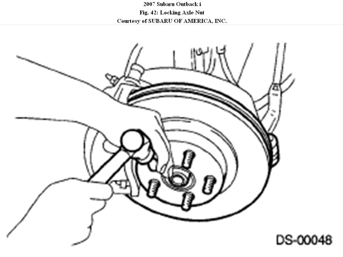
7. After tightening the axle nut, lock it securely.
Fig. 42: Locking Axle Nut
8. Install the wheel and tighten the wheel nuts to specified torque.
Tightening torque: 120 N.M (12.2 kgf-m, 88.5 ft-lb)
Images (Click to make bigger)
SPONSORED LINKS
Tuesday, January 11th, 2011 AT 4:02 PM