First, are video links that shows how to replace brakes and rotors. You can use this as a guide. Here are two videos to handle both 2500, 3500 and 1500 brake pads or shoes replacements with diagrams below to help as well.
https://youtu.be/EMxfb9X3ywE
and
https://youtu.be/uo1RnATyEok
and
https://youtu.be/-Ts8SRUxRc8
and
https://www.2carpros.com/articles/how-to-replace-rear-brake-pads-and-rotors
Here are the directions specific to your vehicle. The attached pics correlate with the directions. Check out the diagrams (Below).
2006 Chevy Truck Silverado 2500 2WD V8-6.0L VIN U
Brake Pads Replacement - Front
Vehicle Brakes and Traction Control Disc Brake System Brake Pad Service and Repair Procedures Brake Pads Replacement - Front
BRAKE PADS REPLACEMENT - FRONT
Brake Pads Replacement - Front (25/3500 Series)
Caution: Refer to Brake Dust Caution in Service Precautions.
Removal Procedure
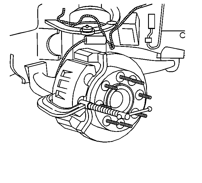
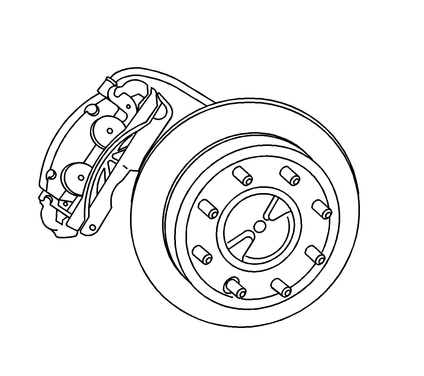
pic 1
1. Inspect the fluid level in the brake master cylinder reservoir.
2. If the fluid level is midway between the maximum - full point, and the minimum allowable level, no fluid needs to be removed from the reservoir before proceeding.
3. If the fluid level is higher than midway between the maximum - full point, and the minimum allowable level, remove fluid to the midway point before proceeding.
4. Remove the tire and wheel assembly.
5. Compress the brake caliper pistons.
1. Install 2 large C-clamps over the top of the caliper housing and against the back of the outboard pad.
2. Slowly tighten the C-clamps until the pistons are pushed completely into the caliper bores.
3. Remove the C-clamps from the caliper.
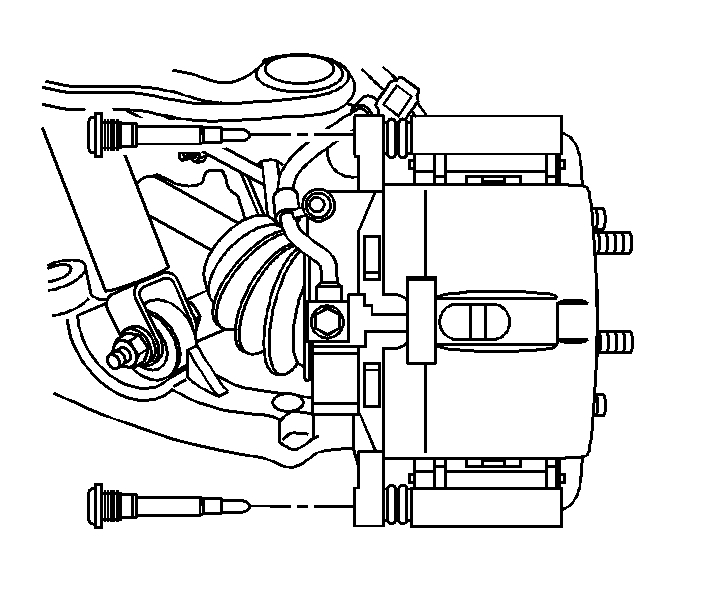
6. Remove the brake caliper bolts.
Caution: Do not depress the brake pedal with the brake rotors/calipers and/or the brake drums removed. Damage to the brake system may result. If brake system damage occurs and is not repaired, vehicle damage and/or personal injury or death may result.
7. Notice: Refer to Brake Caliper Notice in Service Precautions.
Remove the caliper from the caliper bracket. Support the caliper with heavy mechanic's wire or equivalent. DO NOT disconnect the hydraulic brake hose from the caliper.
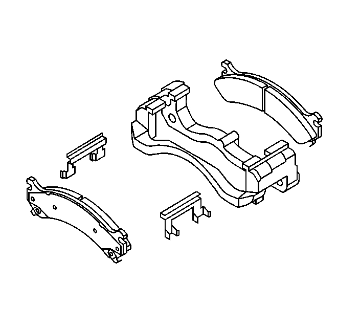
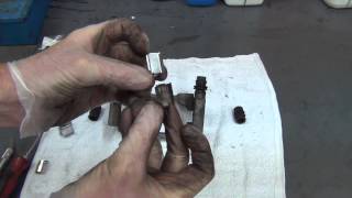
8. Remove the brake pads from the caliper bracket.
9. Remove and discard the anti-rattle clips.
10. Inspect the caliper and caliper bracket.
Installation Procedure
1. Install NEW anti-rattle clips to the caliper bracket.
2. Install the disc brake pads.
2500 Series - inner and outer pad with wear sensor leading.
3500 Series - install the inner and outer pads.
3. Install the caliper to the caliper bracket.
4. Notice: Refer to Fastener Notice in Service Precautions.
Install the brake caliper bolts.
Tighten the bolts to 108 Nm (80 ft. lbs.).
5. Install the tire and wheel assembly.
6. Remove the safety stands.
7. Lower the vehicle.
8. With the engine OFF, gradually apply the brake pedal to approximately 2/3 of its travel distance.
9. Slowly release the brake pedal.
10. Wait 15 seconds, then repeat steps 7-8 until a firm pedal is obtained. This will properly seat the brake caliper pistons and pads.
11. Fill the brake master cylinder reservoir to the proper level with clean brake fluid, if necessary.
12. Burnish the pads and rotors.
_______________________________
Brake Rotor Replacement
2006 Chevy Truck Silverado 2500 2WD V8-6.0L VIN U
Front Brake Rotor Replacement
Vehicle Brakes and Traction Control Disc Brake System Brake Rotor/Disc Service and Repair Removal and Replacement Front Brake Rotor Replacement
FRONT BRAKE ROTOR REPLACEMENT
Brake Rotor Replacement - Front (25/3500 Series)
Tools Required
- J 41013 Rotor Resurfacing Kit
- J 42450-A Wheel Hub Resurfacing Kit
Caution: Refer to Brake Dust Caution in Service Precautions.
Removal Procedure
Notice: Any new rotor must have the protective coating removed from the friction surfaces before being placed in service. Remove the protective coating using denatured alcohol or an equivalent, and wipe the surface clean with clean cloths. Do not use gasoline, kerosene, or other oil base solvents which may leave an oily residue. This residue is damaging to the brake lining and is flammable.
1. Remove the tire and wheel assembly.
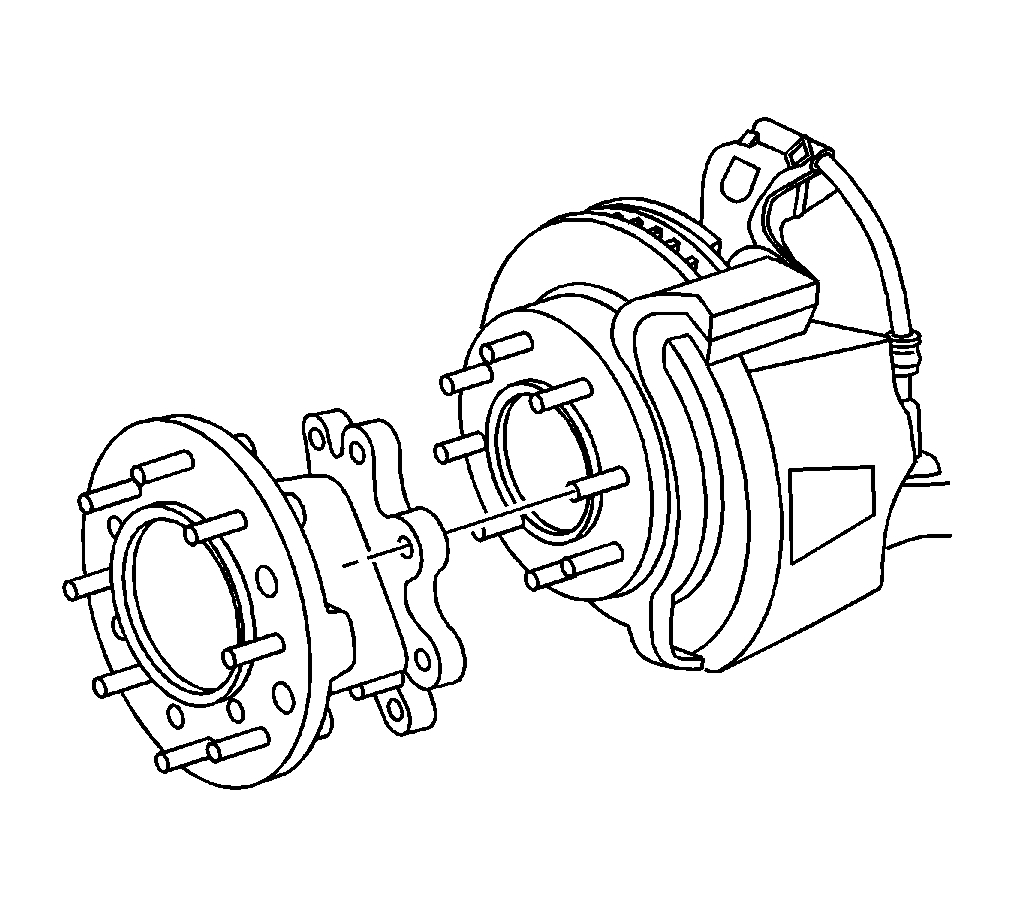
2. Remove the front wheel hub extension, dual wheel vehicles only.
1. Insert a drift or large screwdriver through the brake caliper into one of the brake rotor vanes in order to prevent the rotor from turning.
2. Mark the relationship of the front wheel hub extension to the hub.
3. Remove the front wheel hub extension nuts.
4. Remove the front wheel hub extension from the vehicle. It may be necessary to tap around the perimeter of the hub extension with a rubber mallet to loosen it from the hub.
3. Inspect the fluid level in the brake master cylinder reservoir.
4. If the fluid level is midway between the maximum - full point, and the minimum allowable level, no fluid needs to be removed from the reservoir before proceeding.
5. If the fluid level is higher than midway between the maximum - full point, and the minimum allowable level, remove fluid to the midway point before proceeding.
6. Mark the relationship of the rotor to the hub.
7. Compress the brake caliper pistons.
1. Install 2 large C-clamps over the top of the caliper housing and against the back of the outboard pad.
2. Slowly tighten the C-clamps until the pistons are pushed completely into the caliper bores.
3. Remove the C-clamps from the caliper.
Notice: Refer to Brake Caliper Notice in Service Precautions.
8. Remove the caliper and caliper bracket as an assembly. Support the caliper assembly with heavy mechanic's wire or equivalent. DO NOT disconnect the hydraulic brake flexible hose from the caliper.
9. Remove the brake rotor retaining push nuts from the wheel studs, if applicable.
10. It may be necessary to strike the end of the hub or the rotor with a deadblow hammer to separate the rotor from the hub.
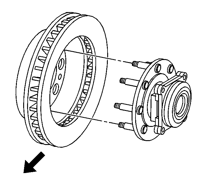
11. Remove the brake rotor.
12. If the rotor is difficult to remove due to corrosion in the hub area use the following procedure to remove the rotor.
1. Clean all the surface areas and the threaded holes of contamination.
2. Generously apply penetrating oil or the equivalent to the hub/rotor area.
3. Insert two M10 x 1.5 bolts or jack screws into the threaded holes of the rotor.
4. Tighten both bolts evenly to force the rotor from the hub.
Installation Procedure
Important: Whenever the brake rotor has been separated from the hub/axle flange, any rust or contaminants should be cleaned from the hub/axle flange and the brake rotor mating surfaces. Failure to do this may result in excessive assembled lateral runout (LRO) of the brake rotor, which could lead to brake pulsation.
1. Use the J 42450-A to clean all rust and contaminants from the mating surface of the hub flange.
2. Use the J 41013 to clean all rust and contaminants from the inside diameter of the hat section of the brake rotor to prevent any foreign material from getting between the brake rotor and the hub flange.
3. Inspect the mating surfaces of the hub/axle flange and the rotor to ensure that there are no foreign particles or debris remaining.
Important: If the rotor was removed using the jack screw method you must ensure that the hub flange is free of nicks or marks caused by this procedure. Remove all raised nicks or marks before installing the rotor.
4. Align the rotor to its original position on the hub (if applicable) and install the rotor.
5. If the rotor was removed and installed as part of a brake system repair, measure the assembled lateral runout (LRO) of the rotor to ensure optimum performance of the disc brakes.
6. If the rotor assembled LRO measurement exceeds the specification, bring the LRO to within specifications.
7. Install the caliper and caliper bracket as an assembly.
8. Perform the following procedure before installing the caliper bracket bolts.
1. Remove all traces of the original adhesive patch.
2. Clean the threads of the bolt with brake parts cleaner or the equivalent and allow to dry.
3. Apply Threadlocker GM P/N 12345493 (Canadian P/N 10953488) to the threads of the bolt.
Notice: Refer to Fastener Notice in Service Precautions.
9. Install the brake caliper bracket bolts.
Tighten the bolts to 300 Nm (221 ft. lbs.).
10. Install the front wheel hub extension (dual wheel vehicles only).
1. Insert a drift or large screwdriver through the brake caliper into one of the brake rotor vanes in order to prevent the rotor from turning.
2. Align and install the front wheel hub extension to the original position on the hub.
Important: Follow the same tightening sequence for the front wheel hub extension that is used on an 8 lug wheel.
3. Install the front wheel hub extension nuts.
Tighten the nuts to 130 Nm (96 ft. lbs.).
11. Install the tire and wheel assembly.
12. With the engine OFF, gradually apply the brake pedal to approximately 2/3 of its travel distance.
13. Slowly release the brake pedal.
14. Wait 15 seconds, then repeat steps 13-14 until a firm pedal is obtained. This will properly seat the caliper pistons and pads.
15. Fill the master cylinder reservoir to the proper level with clean brake fluid, if necessary.
Check out the diagrams (Below). Please let us know if you need anything else to get the problem fixed.
Images (Click to make bigger)
SPONSORED LINKS
Wednesday, February 10th, 2021 AT 2:55 PM