120 code
DTC P0120
CIRCUIT DESCRIPTION
The throttle body assembly contains the following components:
The throttle blade
The throttle actuator motor
The throttle position (TP) sensor 1 and 2
The throttle actuator control (TAC) module
The TAC system monitors the throttle position with 2 sensors. If the powertrain control module (PCM) receives a message from the TAC module that indicates one of the following conditions, DTC P0120 will set:
The TP sensor 1 voltage is outside a predetermined range.
The reference voltage is out of range.
An improper throttle blade minimum position was learned.
DTC DESCRIPTOR
This diagnostic procedure supports the following DTC:
DTC P0120 Throttle Position (TP) Sensor 1 Circuit
CONDITIONS FOR RUNNING THE DTC
DTCs P0606, P2107, P2108 are not set.
The Ignition 1 Signal parameter is in the crank or the run position.
The ignition voltage is more than 5.23 volts.
The communications between the TAC module and the PCM must be valid.
CONDITIONS FOR SETTING THE DTC
The TP sensor 1 voltage is continuously less than 0.376 volts or more than 4.506 volts for longer than 100 ms. OR
The PCM learns a minimum throttle position of more than 0.714 volts. This occurs once per ignition cycle at power-up. OR
The TP sensor reference voltage is less than 4.54 volts for longer than 10 ms, or more than 5.21 volts for longer than 1 second. This test occurs continuously.
ACTION TAKEN WHEN THE DTC SETS
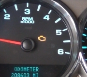
The control module illuminates the malfunction indicator lamp (MIL) when the diagnostic runs and fails.
The control module records the operating conditions at the time the diagnostic fails. The control module stores this information in the Freeze Frame and/or the Failure Records.
The control module commands the TAC system to operate in the Reduced Engine Power mode.
A message center or an indicator displays Reduced Engine Power.
Under certain conditions the control module commands the engine OFF.
CONDITIONS FOR CLEARING THE MIL/DTC
The control module turns OFF the malfunction indicator lamp (MIL) after 3 consecutive ignition cycles that the diagnostic runs and does not fail.
A current DTC, Last Test Failed, clears when the diagnostic runs and passes.
A history DTC clears after 40 consecutive warm-up cycles, if no failures are reported by this or any other emission related diagnostic.
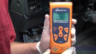
Clear the MIL and the DTC with a scan tool.
1125 pedal sensor
DTC P1125
CIRCUIT DESCRIPTION
The accelerator pedal position (APP) sensor 1 and APP sensor 2 are potentiometer type sensors, each with the following circuits:
A 5-volt reference circuit
A low reference circuit
A signal circuit
The control module provides the APP sensors a 5-volt reference circuit and a low reference circuit. The APP sensors then provide the control module signal voltages proportional to pedal movement. The APP sensor 1 signal voltage is low at rest and increases as the pedal is depressed. The APP sensor 2 signal voltage is also low at rest and increases as the pedal is depressed. One APP sensor DTC will not cause the Reduced Engine Power message to be displayed. Two APP sensor DTCs for the same sensor also will not cause the Reduced Engine Power message to be displayed. However, if 2 or more DTCs are set involving more than one APP sensor, DTC P1125 will set.
DTC DESCRIPTOR
This diagnostic procedure supports the following DTC:
DTC P1125 Accelerator Pedal Position (APP) System
CONDITIONS FOR RUNNING THE DTC
DTCs P0606, P2107, P2108 are not set.
The ignition switch is in the crank or run position.
The Ignition 1 Signal parameter is more than 5.23 volts.
The communications between the throttle actuator control (TAC) module and the powertrain control module (PCM) must be valid.
DTC P1125 runs one time per drive cycle once the above conditions are met.
CONDITIONS FOR SETTING THE DTC
Two APP sensors are out of range or both APP sensors disagree with each other for longer than 18.75 milliseconds.
ACTION TAKEN WHEN THE DTC SETS
The control module illuminates the malfunction indicator lamp (MIL) when the diagnostic runs and fails.
The control module records the operating conditions at the time the diagnostic fails. The control module stores this information in the Freeze Frame and/or the Failure Records.
The control module commands the TAC system to operate in the Reduced Engine Power mode.
A message center or an indicator displays Reduced Engine Power.
Under certain conditions the control module commands the engine OFF.
CONDITIONS FOR CLEARING THE MIL/DTC
The control module turns OFF the malfunction indicator lamp (MIL) after 3 consecutive ignition cycles that the diagnostic runs and does not fail.
A current DTC, Last Test Failed, clears when the diagnostic runs and passes.
A history DTC clears after 40 consecutive warm-up cycles, if no failures are reported by this or any other emission related diagnostic.
Clear the MIL and the DTC with a scan tool.
Thursday, December 27th, 2012 AT 2:51 AM