Hi,
Replacing front brake pads and rotors isn't too hard to do. Since they usually last around 25,000 miles, you can get lifetime parts and never have to pay for parts again.
Let's get started. First, here is a link that shows in general how it's done. You can use this as a guide when working on your vehicle:
https://www.2carpros.com/articles/how-to-replace-front-brake-pads-and-rotors-fwd
Here are the directions specific to your vehicle. The pics below correlate with the directions.
__________________________________________
2005 GMC Truck Yukon/Denali 2WD V8-5.3L VIN Z Flex Fuel
Brake Pads Replacement - Front
Vehicle Brakes and Traction Control Disc Brake System Brake Pad Service and Repair Procedures Brake Pads Replacement - Front
BRAKE PADS REPLACEMENT - FRONT
Brake Pads Replacement - Front
Removal Procedure
Caution: Refer to Brake Dust in Service Precautions.
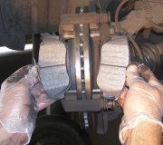
pic 1
1. Inspect the fluid level in the brake master cylinder reservoir.
2. If the brake fluid level is midway between the maximum-full point and the minimum allowable level, no brake fluid needs to be removed from the reservoir before proceeding.
3. If the brake fluid level is higher than midway between the maximum-full point and the minimum allowable level. remove brake fluid to the midway point before proceeding.
4. Raise and support the vehicle. Refer to in Vehicle Lifting.
5. Remove the tire and wheel assembly. Refer to in Tire and Wheel Removal and Installation in Tires and Wheels.
6. Inspect the caliper operation. Refer to Brake Caliper Inspection
Notice: Support the brake caliper with heavy mechanic's wire, or equivalent, whenever it is separated from its mount and the hydraulic flexible brake hose is still connected. Failure to support the caliper in this manner will cause the flexible brake hose to bear the weight of the caliper, which may cause damage to the brake hose and in turn may cause a brake fluid leak.
7. Remove the caliper from the mounting bracket and support the caliper with heavy mechanic's wire or equivalent. DO NOT disconnect the hydraulic brake flexible hose from the caliper. Refer to Brake Caliper Replacement - Front.
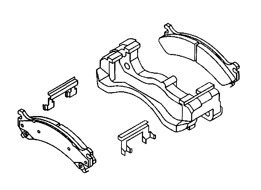
8. Remove the brake pads from the caliper mounting bracket.
9. Remove and discard the anti-rattle clips from the brake caliper mounting bracket.
10. Inspect the caliper and mounting bracket. Refer to Brake Caliper Inspection.
Installation Procedure
pic 2
1. Install new anti-rattle clips to the inside ends of the caliper mounting bracket.
2. Install the brake pads to the caliper mounting bracket.
3. Install the brake caliper. Refer to Brake Caliper Replacement - Front.
4. Install the tire and wheel assembly. Refer to Tire and Wheel Removal and Installation in Tires and Wheels.
5. Remove the safety stands.
6. Lower the vehicle.
7. With the engine OFF, gradually apply the brake pedal to approximately 2/3 of its travel distance.
8. Slowly release the brake pedal.
9. Wait 15 seconds, then repeat steps 7-8 until a firm pedal is obtained. This will properly seat the brake caliper pistons and brake pads.
10. Fill the master cylinder reservoir to the proper level with clean brake fluid. Refer to Master Cylinder Reservoir Filling in Hydraulic Brakes.
11. Burnish the brake pads and rotors. Refer to Burnishing Pads and Rotors.
_____________________________________________________
Rotor Replacement
2005 GMC Truck Yukon/Denali 2WD V8-5.3L VIN Z Flex Fuel
Brake Rotor Replacement - Front
Vehicle Brakes and Traction Control Disc Brake System Brake Rotor/Disc Service and Repair Procedures Brake Rotor Replacement - Front
BRAKE ROTOR REPLACEMENT - FRONT
Brake Rotor Replacement - Front
Caution: Refer to Brake Dust Caution in Service Precautions.
Tools Required
J41013 Rotor Resurfacing Kit
J42450-A Wheel Hub Resurfacing Kit
Removal Procedure
pic 3
Notice: Any new rotor must have the protective coating removed from the friction surfaces before being placed in service. Remove the protective coating using denatured alcohol or an equivalent, and wipe the surface clean with clean cloths. Do not use gasoline, kerosene, or other oil base solvents which may leave an oily residue. This residue is damaging to the brake lining and is flammable.
1. Raise and suitably support the vehicle. Refer to Vehicle Lifting..
2. Remove the tire and wheel assembly. Refer to Tire and Wheel Removal and Installation in Tires and Wheels.
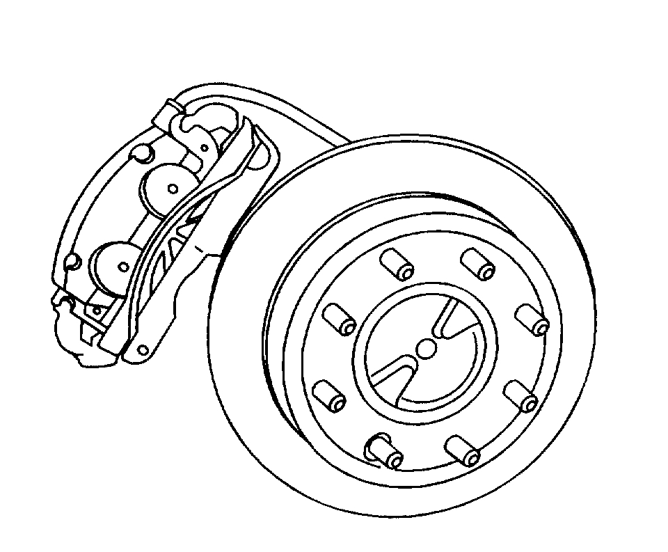
3. Mark the relationship of the rotor to the hub.
4. Install a C-clamp over the body of the brake caliper, with the C-clamp ends against the rear of the caliper body and the outboard disc brake pad.
5. Slowly tighten the C-clamp until the pistons are pushed into the caliper bores enough to remove the caliper from the pads.
pic 4
6. Remove the C-clamp from the caliper.
7. Remove the 2 brake caliper bracket mounting bolts.
Notice: Support the brake caliper with heavy mechanic's wire, or equivalent, whenever it is separated from its mount and the hydraulic flexible brake hose is still connected. Failure to support the caliper in this manner will cause the flexible brake hose to bear the weight of the caliper, which may cause damage to the brake hose and in turn may cause a brake fluid leak.
8. Remove the brake caliper and brake caliper mounting bracket as an assembly and support with heavy mechanic's wire or equivalent. DO NOT disconnect the hydraulic brake flexible hose from the caliper.
9. Remove the rotor retaining push nuts from the wheel studs, if applicable.
10. It may be necessary to strike the end of the hub or the rotor with a deadblow hammer to separate the rotor from the hub.
pic 5
11. Remove the rotor.
12. If the rotor is difficult to remove due to corrosion in the hub area use the following procedure to remove the rotor.
Clean all the surface areas and the threaded holes of contamination.
Generously apply penetrating oil or the equivalent to the hub/rotor area.
Insert (2) M10 x 1.5 bolts into the threaded holes of the rotor.
Tighten both bolts evenly to force the rotor from the hub.
Installation Procedure
pic 6
Important: Whenever the brake rotor has been separated from the hub/axle flange, any rust or contaminants should be cleaned from the hub/axle flange and the brake rotor mating surfaces. Failure to do this may result in excessive assembled Lateral Runout (LRO) of the brake rotor, which could lead to brake pulsation.
1. Use the J42450-A to clean all rust and contaminants from the mating surface of the hub flange.
2. Use the J41013to clean all rust and contaminants from the inside diameter of the hat section of the brake rotor to prevent any foreign material from getting between the brake rotor and the hub flange.
3. Inspect the mating surfaces of the hub/axle flange and the rotor to ensure that there are no foreign particles or debris remaining.
Important: If the rotor was removed using the jack screw method you must ensure that the hub flange is free of nicks or marks caused by this procedure. Remove all raised nicks or marks before installing the rotor.
4. Align the rotor to its original position on the hub, if applicable, and install the rotor.
5. If the brake rotor was removed and installed as part of a brake system repair, measure the assembled Lateral Runout (LRO) of the brake rotor to ensure optimum performance of the disc brakes. Refer to Brake Rotor Assembled Lateral Runout (LRO) Measurement.
6. If the brake rotor assembled LRO measurement exceeds the specification, bring the LRO to within specifications. Refer to Brake Rotor Assembled Lateral Runout (LRO) Correction.
7. Install the caliper and caliper mounting bracket assembly.
8. Perform the following procedure before installing the brake caliper bracket mounting bolts.
Remove all traces of the original adhesive patch.
Clean the threads of the bolt with brake parts cleaner or the equivalent and allow to dry.
Apply Threadlocker GM P/N 12345493 (Canadian P/N 10953488) to the threads of the bolt.
pic 7
Notice: Refer to Fastener Notice in Service Precautions.
9. Install the 2 caliper bracket mounting bolts.
Tighten the brake caliper bracket mounting bolts to 175 Nm (121 ft. lbs.) (15 Series).
Tighten the brake caliper bracket mounting bolts to 300 Nm (221 ft. lbs.) (25 Series).
10. Install the tire and wheel assembly. Refer to Tire and Wheel Removal and Installation in Tires and Wheels.
11. Lower the vehicle.
12. With the engine OFF, gradually apply the brake pedal to approximately 2/3 of its travel distance.
13. Slowly release the brake pedal.
14. Wait 15 seconds, then repeat steps 12-13 until a firm pedal is obtained. This will properly seat the brake caliper pistons and brake pads.
15. Fill the master cylinder reservoir to the proper level with clean brake fluid. Refer to Master Cylinder Reservoir Filling in Hydraulic Brakes.
_________________________________
I hope this helps. Let me know if you have other questions.
Take care and God Bless,
Joe
Images (Click to make bigger)
SPONSORED LINKS
Friday, March 5th, 2021 AT 1:41 PM