There is not specifically a shift pressure control solenoid. There is a line pressure control solenoid, and several shift solenoids, all of which are in the control valve body. It does not show a specific solenoid replacement procedure for any of the solenoids, just a general control valve body replacement procedure. It involves going through the left front wheel well area to remove the side cover. the literature portion is included.
Control Valve Body Cover Replacement
Removal Procedure
•Raise the vehicle. Refer to Lifting and Jacking the Vehicle in General Information.
•Remove the left front wheel and tire assembly. Refer to Tire and Wheel Removal and Installation in Tires and Wheels.
•Remove the left splash shield. Refer to Engine Splash Shield Replacement in Body Front End.
•Remove the front engine mount. Refer to Engine Front Mount Replacement in Engine Mechanical - 3.4L.
•Remove the transaxle oil cooler lines and seals from the transaxle. Refer to Fluid Cooler Pipe Seal Replacement
•Remove the 9 TORX bolts (2) from the control valve body cover (1).
Important: Do not pry with a tool on the transaxle control valve body cover, case or sealing surfaces.
•Remove control valve body cover.
Installation Procedure
-------------------------------------------------------------------
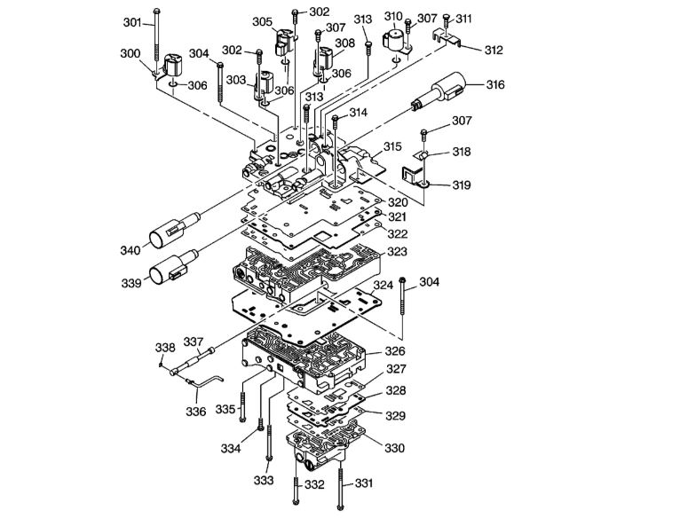
Control Valve Body Replacement
Removal Procedure
Important: Place the transaxle in neutral (N).
•Remove the control valve body cover. Refer to Control Valve Body Cover Replacement .
•Disconnect the wiring harness connectors (1-8).
•Remove the fluid temperature sensor bolt (31).
•Remove the fluid temperature sensor clamp (49).
•Remove the fluid temperature sensor (36) and the O-ring (32) from the control valve body.
•Remove the wiring harness (33) from the automatic transaxle wiring harness clip.
•With a twisting motion remove the complete wiring harness assembly.
•Remove the 2 control valve body bolts/screws (31), control valve body fluid passage cover (37) and gasket (38).
•Remove the 6 control valve body mounting bolts/screws (1-6).
•While holding the control valve body assembly, disconnect the manual shift detent lever assembly (710) from the manual valve link (336).
•Move the detent lever assembly clockwise for ease of removing the manual valve.
•Remove the control valve body assembly (39).
•Remove the 2 transaxle case fluid passage seals (86).
Installation Procedure
•Install 2 new transaxle case fluid passage seals (86) into the transaxle case fluid ports.
•While holding the control valve body assembly (39), connect the manual valve link (336) to the manual shift detent lever assembly (710).
•Install the 6 control valve body assembly to transaxle case bolts and hand tighten.
Notice: Refer to Fastener Notice in the Preface section.
•Tighten the control valve body assembly-to-transaxle case bolts in sequence.
Tighten
Tighten the bolts to 10 N·m (89 lb in).
•Install a new control valve body fluid passage cover gasket (38).
•Install the control valve body fluid passage cover (37).
•Install the 2 control valve body bolts (31).
Tighten
Tighten the bolt to 10 N·m (89 lb in).
•Apply GM T-IV automatic transaxle fluid GM P/N 88900925 to a new transaxle wiring connector O-ring seal (46).
•Install a new transaxle wiring connector O-ring seal (46) onto the transaxle wiring harness assembly (33).
•Install the transaxle wiring harness assembly (33) into the transaxle case through the wiring harness bore.
•Apply GM T-IV automatic transaxle fluid GM P/N 88900925 to a new transaxle fluid temperature sensor O-ring seal (32).
•Install a new transaxle fluid temperature sensor O-ring seal (32) into the groove of the transaxle fluid temperature sensor (36).
•Install the transaxle fluid temperature sensor (36) into the front control valve body fluid temperature sensor bore.
•Install the transaxle fluid temperature sensor clip (49).
•Install the fluid temperature sensor bolt (31).
Tighten
Tighten the bolt to 10 N·m (89 lb in).
•Connect the 8 solenoid wire connectors as follows:
• 1 blue
• 2 black
• 3 green
• 4 black
• 5 blue
• 6 gray
• 7 brown
• 8 black
•Install the control valve body cover. Refer to Control Valve Body Cover Replacement .
•Perform the transmission adaptive learn procedure. Refer to Transmission Adaptive Learn .
Jul 27, 2011 at 4:43 AM