DTC P0059
CIRCUIT DESCRIPTION
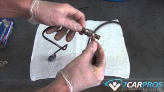
The heated oxygen sensor (HO2S) must reach operating temperature to provide an accurate voltage signal. A heating element inside the HO2S minimizes the time required for the sensor to reach operating temperature. Voltage is provided to the heater by the ignition 1 voltage circuit through a fuse. With the engine running, ground is provided to the heater by the HO2S heater low control circuit, through a low side driver within the powertrain control module (PCM). The PCM commands the heater ON or OFF to maintain a specific HO2S operating temperature range. The PCM determines the temperature by measuring the current flow through the heater. When the heater is in the ON state, the PCM will pulse the heater OFF for a duration of 50 ms, once per second. The PCM calculates the heater resistance on a cold start. This diagnostic will only run once per ignition cycle. If the PCM detects that the heater calculated resistance is not within the expected range, the following DTCs will set:
DTC P0053 for HO2S bank 1 sensor 1
DTC P0054 for HO2S bank 1 sensor 2
DTC P0059 for HO2S bank 2 sensor 1
DTC DESCRIPTORS
This diagnostic procedure supports the following DTCs:
DTC P0053 HO2S Heater Resistance Bank 1 Sensor 1
DTC P0054 HO2S Heater Resistance Bank 1 Sensor 2
DTC P0059 HO2S Heater Resistance Bank 2 Sensor 1
CONDITIONS FOR RUNNING THE DTC
DTCs P0112, P0113, P0116, P0117, P0118, P0128, P2610 are not set.
The ignition is OFF for more than 10 hours.
The ECT Sensor parameter is between 0-40°C (32-104°F) at engine start-up.
The ECT Sensor parameter minus the IAT Sensor parameter is less than 8°C (14°F) at engine start-up.
The engine is started.
The above conditions are met for up to 100 seconds.
This diagnostic runs 1 time per valid cold start once the above conditions are met.
CONDITIONS FOR SETTING THE DTC
The PCM detects that the affected HO2S heater calculated resistance is not within an expected range at engine start-up for 1 second.
ACTION TAKEN WHEN THE DTC SETS
The control module illuminates the malfunction indicator lamp (MIL) on the second consecutive ignition cycle that the diagnostic runs and fails.
The control module records the operating conditions at the time the diagnostic fails. The first time the diagnostic fails, the control module stores this information in the Failure Records. If the diagnostic reports a failure on the second consecutive ignition cycle, the control module records the operating conditions at the time of the failure. The control module writes the operating conditions to the Freeze Frame and updates the Failure Records.
CONDITIONS FOR CLEARING THE MIL/DTC
The control module turns OFF the malfunction indicator lamp (MIL) after 3 consecutive ignition cycles that the diagnostic runs and does not fail.
A current DTC, Last Test Failed, clears when the diagnostic runs and passes.
A history DTC clears after 40 consecutive warm-up cycles, if no failures are reported by this or any other emission related diagnostic.
Clear the MIL and the DTC with a scan tool.
TEST DESCRIPTION
Steps 1 - 7
Steps 8 - 19
Steps 20 - 21
The number below refers to the step number on the diagnostic table.
With no fault present, the test lamp will blink once per second.
DTC P0155
CIRCUIT DESCRIPTION
The heated oxygen sensor (HO2S) must reach operating temperature to provide an accurate voltage signal. A heating element inside the HO2S minimizes the time required for the sensor to reach operating temperature. Voltage is provided to the heater by the ignition 1 voltage circuit through a fuse. With the engine running, ground is provided to the heater by the HO2S heater low control circuit, through a low side driver within the powertrain control module (PCM). The PCM commands the heater ON or OFF to maintain a specific HO2S operating temperature range. The PCM determines the temperature by measuring the current flow through the heater. When the heater is in the ON state, the PCM will pulse the heater OFF for a duration of 50 ms, once per second. When the heater is in the OFF state, the PCM will pulse the heater ON for a duration of 50 ms, once per second. The PCM monitors the heater current with the engine running. This diagnostic will only run once per ignition cycle. If the PCM detects that the heater current is not within an expected range, the following DTCs will set:
DTC P0135 for HO2S bank 1 sensor 1
DTC P0141 for HO2S bank 1 sensor 2
DTC P0155 for HO2S bank 2 sensor 1
DTC DESCRIPTORS
This diagnostic procedure supports the following DTCs:
DTC P0135 HO2S Heater Performance Bank 1 Sensor 1
DTC P0141 HO2S Heater Performance Bank 1 Sensor 2
DTC P0155 HO2S Heater Performance Bank 2 Sensor 1
CONDITIONS FOR RUNNING THE DTC
DTCs P0053, P0054, P0059, P0101, P0102, P0103, P0106, P0107, P0108, P0112, P0113, P0116, P0117, P0118, P0121, P0122, P0123, P0128, P0200, P0442, P0446, P0452, P0453, P0455, P0496 are not set.
The ECT Sensor parameter is more than 50°C (122°F).
The Ignition 1 Signal parameter is between 10-18 volts.
The MAF Sensor parameter is between 3-40 g/s.
Then Engine Speed parameter is between 500-3,000 RPM.
The Engine Run Time parameter is more than 120 seconds.
The above conditions are met for2 seconds.
This diagnostic runs one time per drive cycle once the above conditions are met.
CONDITIONS FOR SETTING THE DTC
The PCM detects that the affected HO2S Heater Current parameter is more than 1.375 amps or less than 0.25 amps.
The above condition is met for 10 seconds.
ACTION TAKEN WHEN THE DTC SETS
The control module illuminates the malfunction indicator lamp (MIL) on the second consecutive ignition cycle that the diagnostic runs and fails.
The control module records the operating conditions at the time the diagnostic fails. The first time the diagnostic fails, the control module stores this information in the Failure Records. If the diagnostic reports a failure on the second consecutive ignition cycle, the control module records the operating conditions at the time of the failure. The control module writes the operating conditions to the Freeze Frame and updates the Failure Records.
CONDITIONS FOR CLEARING THE MIL/DTC
The control module turns OFF the malfunction indicator lamp (MIL) after 3 consecutive ignition cycles that the diagnostic runs and does not fail.
A current DTC, Last Test Failed, clears when the diagnostic runs and passes.
A history DTC clears after 40 consecutive warm-up cycles, if no failures are reported by this or any other emission related diagnostic.
Clear the MIL and the DTC with a scan tool.
SPONSORED LINKS
Saturday, December 15th, 2012 AT 9:41 PM