I have the complete manual on this car but it is very extensive, I'm sending you the fuel section in trying to find the programming section, let me know what sections you want me to send you.
Fuel System 2.5L and 3.0L vehicles Fig. 30: Fuel System Components (2.5L And 3.0L) Courtesy of JAGUAR CARS, INC. The electronic returnless fuel system utilized has the following advantages: reduced fuel tank vapor. Requires less electrical power. Does not require a fuel return line. The intelligence of this system is contained within the engine control module (ECM). The ECM determines the required fuel flow and communicates this information to the fuel pump controller. The fuel pump controller has the fuel pump driver functions fully integrated into the microprocessor. The ECM calculates the frequency and determines the current required by the fuel pump to maintain the correct fuel pressure at the fuel injectors. The fuel tank is of a saddle design which incorporates two sender units. The right-hand side houses the fuel pump module. The left-hand side houses the transfer pump module. CAUTION:The use of supplementary oil or fuel additives is not approved unless specified by Jaguar Cars in the form of a service communication or directive. Fuel is supplied at high pressure to the injectors via a fuel rail which incorporates a fuel pressure and a fuel temperature sensor. The ECM increases the fuel pressure to minimize fuel vapor formation to maintain fuel flow across the injectors. An inertia type fuel cut-off switch will cut power to the fuel pump module in the event of an accident.
Diagnosis and Testing Fuel System Verify the customer concern. Visually inspect for obvious signs of mechanical or electrical damage. If an obvious cause for an observed or reported concern is found, correct the cause (if possible) before proceeding to the next step. If the concern is not visually evident, refer to the Symptom Chart.
DIAGNOSTIC TROUBLE CODE INDEX DTCDescriptionPossible SourceAction P1233, P1235Fuel Pump Primary Circuit FailureDamaged harness. Connector loose or corroded. Connector pin(s) bent or tracking between connections. Damaged GROUND. 'Popped' inertia switch. GO to PINPOINT TEST A. B1201, P0460Fuel Sender Circuit FailureWorn or damaged sensor tracks. Damaged Harness. Connector loose or corroded. Connector pin(s) bent or tracking between connections. Fuel level sensor to instrument cluster circuits intermittent short or open circuit or high resistance. Fuel level sensor failure. Instrument cluster fault (incorrect fuel level data). GO to PINPOINT TEST B.
PINPOINT TEST A: P1233, P1235-Fuel Pump Primary Circuit Failure A1: CHECK THE POSITIVE SUPPLY TO THE FUEL PUMP Switch the ignition to the OFF position. Disconnect the fuel pump electrical connector FT002. Switch the ignition to the RUN position. Measure the pulse width modulation voltage between the fuel pump electrical connector FT002 pin 2, (KB) and GROUND. Is there a 1 second, 12 volts voltage signal after the ignition is switched on? _> Yes GO to Pinpoint Test G92510t2 : CHECK THE GROUND SUPPLY TO THE FUEL PUMP. _> No GO to Pinpoint Test G92510t5 : CHECK THE VOLTAGE OUTPUT AT THE FUEL PUMP CONTROLLER. A2: CHECK THE GROUND SUPPLY TO THE FUEL PUMP Switch the ignition to the OFF position. Measure the resistance between the fuel pump electrical connector FT002 pin 4, (B) and GROUND. Is the resistance less than 0.5 Ohm? _> Yes INSTALL a new fuel pump. CLEAR DTC. TEST the system for normal operation. _> No GO to Pinpoint Test G92510t7 : CHECK THE GROUND SUPPLY AT THE FUEL PUMP CONTROLLER
A3: CHECK THE POSITIVE SUPPLY TO THE FUEL PUMP CONTROLLER Switch the ignition to the RUN position. 2. Measure the voltage at the fuel pump controller CA105 pin 9. Is the voltage less than 10.5 Volts? _> Yes GO to Pinpoint Test G92510t4 : CHECK THE FUEL PUMP CONTROLLER VOLTAGE SUPPLY FUSE. _> No GO to Pinpoint Test G92510t10 : CHECK THE SWITCHABLE SUPPLY TO THE FUEL PUMP CONTROLLER. A4: CHECK THE FUEL PUMP CONTROLLER VOLTAGE SUPPLY FUSE Measure the voltage at the fuel pump controller supply fuse. Is the voltage less than 10.5 Volts? _> Yes GO to Pinpoint Test G92510t12 : CHECK THE POSITIVE SUPPLY TO THE IGNITION RELAY. _> No REPAIR the circuit between the central electrical junction box (CEJB) and the fuel pump controller. CLEAR DTC. TEST the system for normal operation. A5: CHECK THE VOLTAGE OUTPUT AT THE FUEL PUMP CONTROLLER Switch the ignition to the OFF position. Disconnect the fuel pump controller electrical connector CA105. Switch the ignition to the RUN position. Measure the pulse width modulation voltage between the fuel pump controller electrical connector CA105 pin 10 and GROUND. Is there a 1 second 12 volts voltage signal after the ignition is switched on? _> Yes GO to Pinpoint Test G92510t6 : CHECK THE CONTINUITY BETWEEN THE FUEL PUMP CONTROLLER AND THE FUEL PUMP. _> No GO to Pinpoint Test G92510t3 : CHECK THE POSITIVE SUPPLY TO THE FUEL PUMP CONTROLLER.
A6: CHECK THE CONTINUITY BETWEEN THE FUEL PUMP CONTROLLER AND THE FUEL PUMP Measure the resistance between the fuel pump controller connector CA105 pin 10, (R) and fuel pump electrical connector FT002 pin 2, (KB). Is the resistance less than 0.5 Ohm? _> Yes INSTALL a new fuel pump controller. CLEAR DTC. TEST the system for normal operation. _> No REPAIR the circuit between the fuel pump controller CA105 pin 10, (R) and the fuel pump electrical connector FT002 pin 2, (KB). CLEAR DTC. TEST the system for normal operation. A7: CHECK THE GROUND SUPPLY AT THE FUEL PUMP CONTROLLER Switch the ignition to the OFF position. Measure the resistance between the fuel pump controller electrical connector CA105 pin 3, (Y) and GROUND. Is the resistance less than 0.5 Ohm? _> Yes GO to Pinpoint Test G92510t8 : CHECK THE CONTINUITY BETWEEN THE FUEL PUMP AND THE FUEL PUMP CONTROLLER. _> No GO to Pinpoint Test G92510t9 : CHECK THE GROUND SUPPLY TO THE FUEL PUMP CONTROLLER. A8: CHECK THE CONTINUITY BETWEEN THE FUEL PUMP AND THE FUEL PUMP CONTROLLER Measure the resistance between the fuel pump connector FT002 pin 4, (B) and the fuel pump controller connector CA105pin3(Y). Is the resistance less than 0.5 Ohms? _> Yes GO to Pinpoint Test G92510t9 : CHECK THE GROUND SUPPLY TO THE FUEL PUMP CONTROLLER. _> No REPAIR the circuit between the fuel pump FT002 pin 4, (B) and the fuel pump controller CA105 pin 3, (Y). CLEAR DTC. TEST the system for normal operation.
A9: CHECK THE GROUND SUPPLY TO THE FUEL PUMP CONTROLLER Switch the ignition to the OFF position. Measure the resistance between the fuel pump controller CA105 pin 2, and GROUND. Is the resistance less than 0.5 Ohm? _> Yes REPAIR the circuit between the fuel pump controller CA105 pin 2, (B) and GROUND. CLEAR DTC. TEST the system for normal operation. _> No INSTALL a new fuel pump controller. CLEAR DTC. TEST the system for normal operation. A10: CHECK THE SWITCHABLE SUPPLY TO THE FUEL PUMP CONTROLLER Switch the ignition to the OFF position. Disconnect the fuel pump controller electrical connector CA105. Switch the ignition to the RUN position. Measure the pulse width modulation frequency between the fuel pump controller electrical connector CA105 pin 1, (N) and GROUND. Is the frequency 250 Hz, 1-50% duty? _> Yes INSTALL a new fuel pump controller. CLEAR DTC. TEST the system for normal operation. _> No GO to Pinpoint Test G92510t11 : CHECK THE CONTINUITY BETWEEN THE FUEL PUMP CONTROLLER AND THE ECM. A11: CHECK THE CONTINUITY BETWEEN THE FUEL PUMP CONTROLLER AND THE ECM Switch the ignition to the OFF position. Disconnect the ECM electrical connector EN016. Measure the resistance between the fuel pump controller electrical connector CA105 pin 1, (N) and the ECM electrical connector EN106pin27, (N). Is the resistance less than 0.5 Ohm? _> Yes INSTALL a new ECM. CLEAR DTC. TEST the system for normal operation. _> No REPAIR the circuit between the fuel pump controller electrical connector CA105 pin 1, (N) and the ECM electrical connector EN106 pin 27, (N). CLEAR DTC. TEST the system for normal operation.
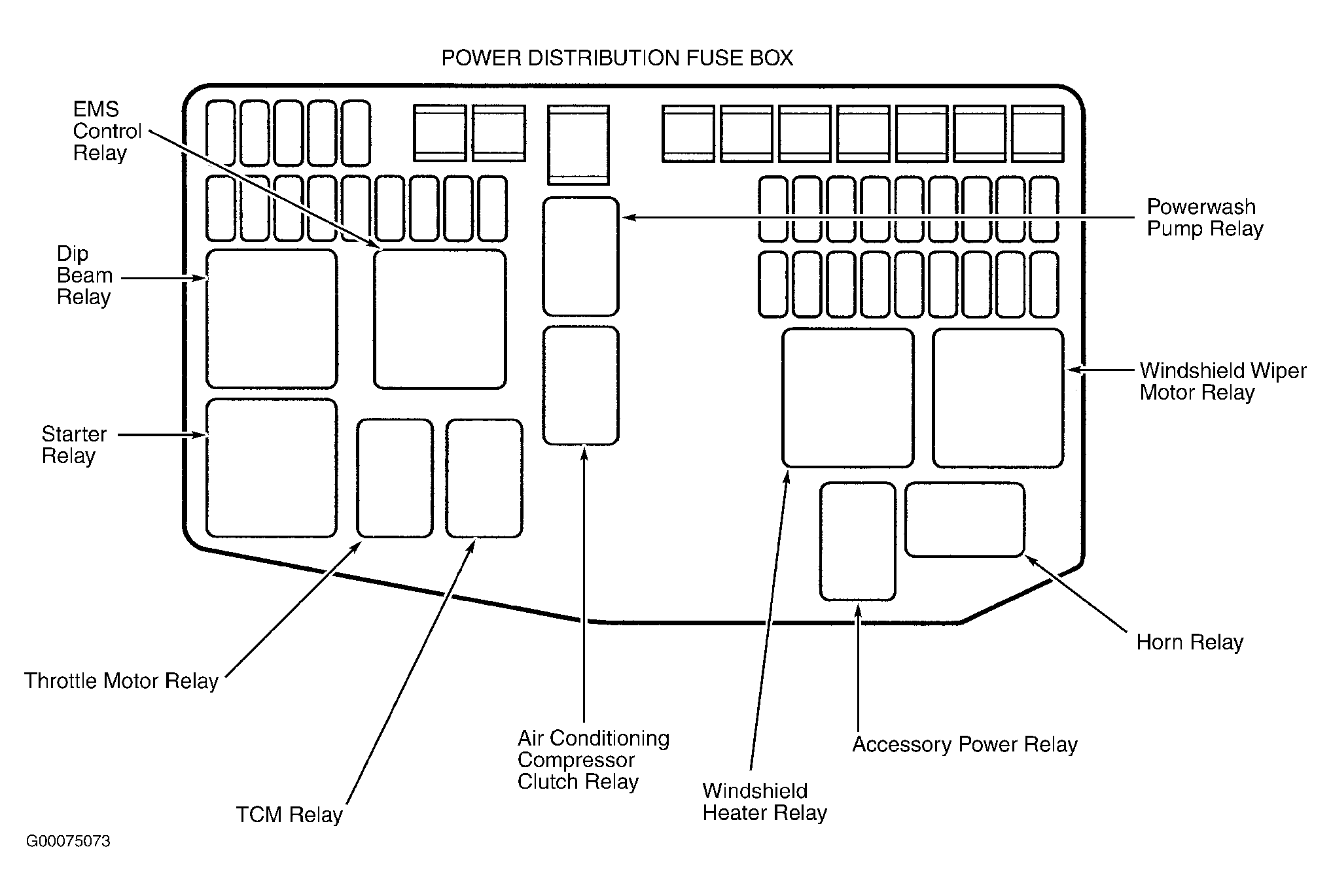
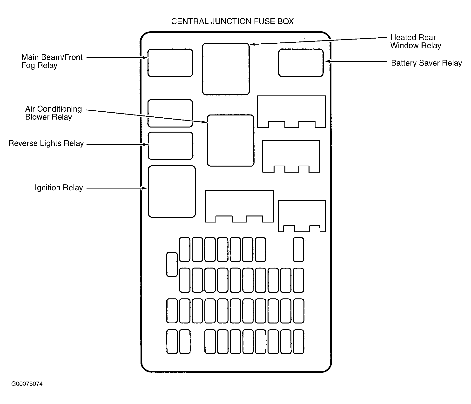
A12: CHECK THE POSITIVE SUPPLY TO THE IGNITION RELAY Switch the ignition to the OFF position. Disconnect the central electrical junction box (CEJB) electrical connector IP003. Switch the ignition to the RUN position. Measure the voltage between the CEJB electrical connector IP003 pin 1, (GU) and GROUND. Is the voltage less than 10.5 Volts? _> Yes GO to Pinpoint Test G92510t13 : CHECK THE POSITIVE SUPPLY TO THE INERTIA SWITCH. _> No INSTALL a new ignition relay R18. CLEAR DTC. TEST the system for normal operation. A13: CHECK THE POSITIVE SUPPLY TO THE INERTIA SWITCH Switch the ignition to the OFF position. Disconnect the inertia switch electrical connector IP132. Switch the ignition to the RUN position. Measure the voltage between the inertia switch electrical connector IP132 pin 3, (GO) and GROUND. Is the voltage less than 10.5 Volts? _> Yes GO to Pinpoint Test G92510t14 : CHECK THE INERTIA SWITCH VOLTAGE SUPPLY AT THE IGNITION SWITCH. _> No GO to Pinpoint Test G92510t15 : CHECK THE CONTINUITY BETWEEN THE CEJB AND THE INERTIA SWITCH.
A14: CHECK THE INERTIA SWITCH VOLTAGE SUPPLY AT THE IGNITION SWITCH Switch the ignition to the OFF position. Remove the ignition switch electrical connector IP018. Switch the ignition to the RUN position. Measure the voltage between the ignition switch electrical connector IP018 pin 1 and GROUND. Is the voltage less than 10.5 Volts? _> Yes INSTALL a new ignition switch. CLEAR DTC. TEST the system for normal operation. _> No REPAIR the circuit between the ignition switch and the inertia switch. CLEAR DTC. TEST system for normal operation. A15: CHECK THE CONTINUITY BETWEEN THE CEJB AND THE INERTIA SWITCH Switch the ignition switch to the OFF position. Measure the resistance between the CEJB electrical connector IP003 pin 1, (GU) and the inertia switch electrical connector IP132 pin 1, (GU) Is the resistance less than 0.5 Ohm? _> Yes INSTALL a new inertia switch. CLEAR DTC. TEST the system for normal operation. _> No REPAIR the circuit between the CEJB electrical connector IP003 pin 1, (GU) and the inertia switch electrical connector IP132 pin 1, (GU). CLEAR DTC. TEST the system for normal operation. PINPOINT TEST B: B1201, P0460-Fuel Sender Circuit Failure B1: CHECK THE VOLTAGE SUPPLY TO THE FUEL TANK ELECTRICAL CONNECTOR Switch the ignition to the OFF position. Disconnect the fuel tank electrical connector CA005. Switch the ignition to the RUN position. Measure the voltage at the fuel tank electrical connector between: CA005 pin 1, (WU) and GROUND CA005 pin 2, (WB) and GROUND Is the voltage greater than 10.5 Volts? _> Yes
A14: CHECK THE INERTIA SWITCH VOLTAGE SUPPLY AT THE IGNITION SWITCH Switch the ignition to the OFF position. Remove the ignition switch electrical connector IP018. Switch the ignition to the RUN position. Measure the voltage between the ignition switch electrical connector IP018 pin 1 and GROUND. Is the voltage less than 10.5 Volts? _> Yes INSTALL a new ignition switch. CLEAR DTC. TEST the system for normal operation. _> No REPAIR the circuit between the ignition switch and the inertia switch. CLEAR DTC. TEST system for normal operation. A15: CHECK THE CONTINUITY BETWEEN THE CEJB AND THE INERTIA SWITCH Switch the ignition switch to the OFF position. Measure the resistance between the CEJB electrical connector IP003 pin 1, (GU) and the inertia switch electrical connector IP132 pin 1, (GU) Is the resistance less than 0.5 Ohm? _> Yes INSTALL a new inertia switch. CLEAR DTC. TEST the system for normal operation. _> No REPAIR the circuit between the CEJB electrical connector IP003 pin 1, (GU) and the inertia switch electrical connector IP132 pin 1, (GU). CLEAR DTC. TEST the system for normal operation. PINPOINT TEST B: B1201, P0460-Fuel Sender Circuit Failure B1: CHECK THE VOLTAGE SUPPLY TO THE FUEL TANK ELECTRICAL CONNECTOR Switch the ignition to the OFF position. Disconnect the fuel tank electrical connector CA005. Switch the ignition to the RUN position. Measure the voltage at the fuel tank electrical connector between: CA005 pin 1, (WU) and GROUND CA005 pin 2, (WB) and GROUND Is the voltage greater than 10.5 Volts? _> Yes
B4: CHECK THE RESISTANCE AT THE FUEL LEVEL SENSORS Remove the fuel tank. For additional information, refer to FUEL TANK - 2.5L/3.0L. Disconnect the fuel sensor electrical connectors: FT002 FT003 Measure the resistance between the sensor electrical connectors: FT002 pin 1 and FT002 pin 3 FT003 pin 1 and FT003 pin 3 Is the resistance between 16 and 160 Ohms? _> Yes REPAIR the relevant circuit. CLEAR DTC. TEST the system for normal operation. _> No INSTALL the relevant new fuel level sensor. CLEAR DTC. TEST the system for normal operation. B5: CHECK THE GROUND SUPPLY FROM THE INSTRUMENT CLUSTER Disconnect the instrument cluster electrical connector IP010. Measure the resistance at the instrument cluster between IP010 pin 9 and GROUND. Is the resistance less than 0.5 Ohm? _> Yes REPAIR the circuit between the instrument cluster IP010 pin 9, (B) and the fuel tank electrical connector CA005 pin 3, (B). CLEAR DTC. TEST the system for normal operation. _> No INSTALL a new instrument cluster. CLEAR DTC. TEST the system for normal operation.
Images (Click to make bigger)
Friday, January 10th, 2020 AT 11:34 AM
(Merged)