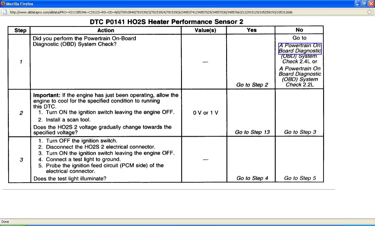
Your going to have to follow the trouble tree to figure this one out i posted the trouble tree wire diagram and code description.Let me know what you find and we will work thru it and figure it out.
Circuit Description
In order to control emissions, a catalytic converter converts any harmful exhaust emissions into harmless water vapor and carbon dioxide.
The PCM has the capability to monitor this process by using a Rear Heated Oxygen Sensor (HO2S 2). The HO2S 2 sensor, located in the exhaust stream past the catalytic converter, produces an output signal which indicates the storage capacity of the catalyst. This in turn indicates the catalysts ability to convert the exhaust emissions effectively. If the catalyst is functioning properly, the HO2S 2 signal will be far less active than the signal produced by the front Oxygen Sensor (O2S 1).
Replace the entire HO2S 2 sensor assembly (Do not attempt to repair the HO2S 2) if the following conditions exist:
* Damaged wiring
* Damaged electrical connector
* Damaged terminal(s)
Obstruction of the air reference and degrade HO2S 2 performance could result in any attempt to repair the above conditions.
The HO2S 2 must have a clean air reference in order for the HO2S 2 sensor to function properly. This clean air reference is obtained by way of the HO2S 2 wire(s).
Conditions for Running the DTC
* Engine Coolant Temperature (ECT) less than 40°C (104°F).
* Intake Air Temperature (IAT) less than 40°C (104°F).
* Difference between ECT and IAT is less than 7°C (45°F).
* Throttle Position (TP) is less than 18%.
Conditions for Setting the DTC
HO2S 2 voltage increases less than 150 mV in 100 to 190 seconds.
Action Taken When the DTC Sets
* The Malfunction Indicator Lamp (MIL) will illuminate after two consecutive ignition cycles in which the diagnostic runs with the malfunction present.
* The PCM will record the operating conditions at the time that the diagnostic fails. This information will store in the Freeze Frame and Failure Records buffers.
* A history DTC stores.
* The coolant fan turns ON.
Conditions for Clearing the MIL/DTC
* The MIL will turn OFF after three consecutive ignition cycles in which the diagnostic runs without a fault.
* A history DTC will clear after 40 consecutive warm up cycles without a fault.
* The MIL/DTCs can be cleared by using the scan tool.
Diagnostic Aids
An intermittent could be the result of the following conditions:
* Poor electrical connection
* Moisture in the connector/wiring
* Rubbed through wire insulation
* Broken wire inside of the insulation
Check for a poor electrical connection or a damaged harness. Inspect the harness electrical connectors for the following conditions:
* Improper mating
* Broken locks
* Improperly formed electrical connectors
* Damaged terminals
* A poor terminal to wire connection
* A damaged harness
Replace the entire HO2S 2 assembly. Do not attempt to repair the HO2S 2 if the following conditions exist:
* Damaged wiring
* Damaged electrical connector
* Damaged terminals
Obstruction of the air reference and degrade HO2S 2 performance could result in any attempt to repair the above conditions.
The HO2S 2 must have a clean air reference in order for the HO2S 2 to function properly. This clean air reference is obtained by way of the HO2S 2 wires.
Test Description
An example Test Description follows:
1. The Powertrain OBD System Check prompts you to complete some of the basic checks and to store the freeze frame and failure records data on the scan tool if applicable. This creates an electronic copy of the data captured when the malfunction occurred. The scan tool stores this data for later reference.
2. This step determines if DTC P0141 is the result of a hard malfunction or an intermittent condition. With the ignition switch ON and the engine OFF, the HO2S 2 voltage displayed on the scan tool should change within several minutes towards 0 or 1 volt, indicating that the heater is working properly.
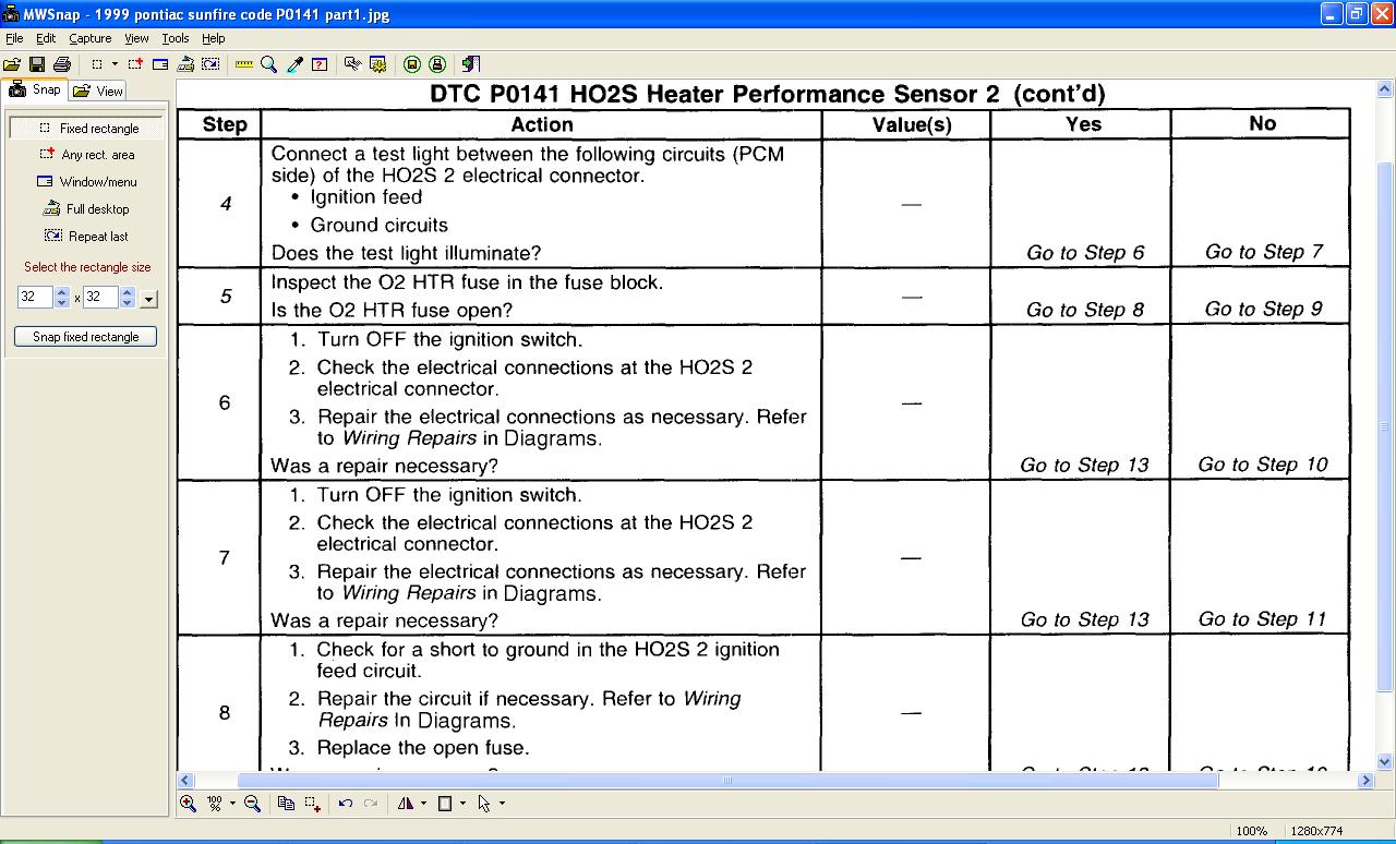
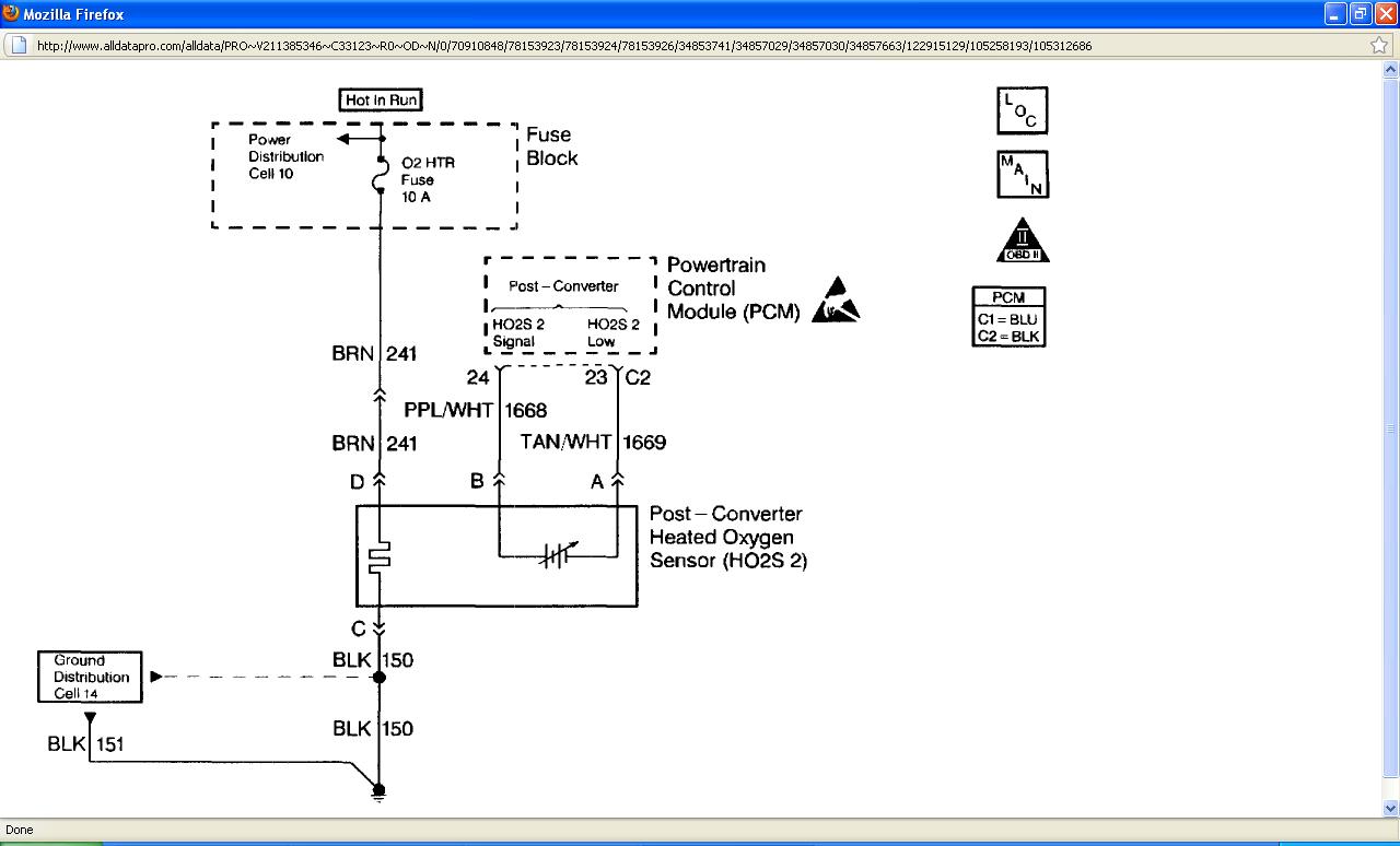
3. Probing terminal D of the HO2S 2 electrical connector verifies if the voltage is available to the HO2S 2 heater.
4. If the voltage is available at the electrical connector, then the connector becomes a good voltage source to check for a ground at terminal C.
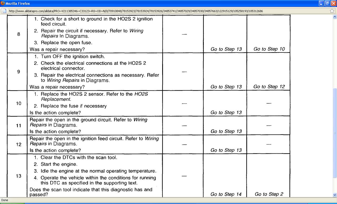
5. This step determines if the voltage is not available at the HO2S 2 due to an open 02 fuse or open ignition feed circuit. If the fuse is open, determine if the open fuse was due to a short in the ignition feed circuit or shorted HO2S 2 before replacing the fuse.
Images (Click to enlarge)
Mar 29, 2011 at 5:47 PM