With a scan tool that can read live data from the MAF take reading, at sea level it should.d read 159hz +/- 6hz
P0113 IAT sensor probably missing from the MAF, replace the MAF with a Ford MAF, not an aftermarket one, some look the same but dont have the right pins. After replacing the MAF, clear the keep alive memory by removing the negative battery cable for a few minutes(5) at least. If you want to test it, here's how:
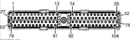
2) DTC P0102: Low MAF Sensor Signal To PCM Check for broken or loose air outlet tube clamps at throttle body and air cleaner assembly. Check for holes and cracks in air outlet tube. Check for worn gaskets between MAF sensor and air cleaner. Repair as necessary. If no problems are detected, start engine and allow it to idle. Check for DTCs. If KOER DTC P0505 is present, go to TEST KE, step 2). On A/T models, if engine stalls or cannot maintain idle speed, go to step 7). If KOER DTC P0505 is not present and engine idles okay, raise engine speed to 1500 RPM for 5 seconds, then return to idle. Using scan tool, select MAF V PID from PID/DATA monitor menu. If MAF V PID voltage is less than .23 volt, turn ignition off and go to step 4). If MAF V PID voltage is .23 volt or more, go to next step. 3) KOEO/KOER DTC P1101: MAF Output Voltage Ensure MAF sensor is connected properly. If MAF sensor is not connected properly, repair as necessary and retest. Start engine and allow it to idle. Using scan tool, select MAF V PID from PID/DATA monitor menu. If MAF V PID voltage is .46-2.44 volts, no problem is indicated at this time. Turn ignition off and go to TEST Z . If MAF V PID voltage is not .46-2.44 volts, turn ignition off and go to next step. 4) Check VPWR Voltage To MAF Sensor Disconnect MAF sensor. Turn ignition on. Measure voltage between ground and VPWR terminal at MAF sensor wiring harness connector. If voltage is more than 10.5 volts, go to next step. If voltage is not more than 10.5 volts, locate and repair open in VPWR circuit. 5) Check PWR GND Circuit Measure voltage between positive battery terminal and PWR GND terminal at MAF sensor wiring harness connector. If voltage is more than 10 volts, turn ignition off and go to next step. If voltage is not more than 10 volts, locate and repair open in PWR GND circuit. 6) Check Resistance Of VPWR Circuit Turn ignition off. Leave MAF sensor disconnected. Disconnect PCM 104-pin connector. Inspect connector for loose, damaged or corroded terminals. Repair as necessary. Measure resistance between VPWR terminal at MAF sensor wiring harness connector and PCM connector pin No. 71. If resistance is less than 5 ohms, go to next step. If resistance is 5 ohms or more, repair open in VPWR circuit. Reset Keep-Alive Memory (KAM). See RESETTING KEEP-ALIVE MEMORY (KAM) under CLEARING CODES. 7) Check MAF Circuit For Short To Ground Or MAF RTN Circuit Disconnect scan tool Data Link Connector (DLC). Measure resistance between PCM connector pin No. 88 (MAF SIG) and pins No. 36 (MAF RTN), 51, 77 and 103 (PWR GND). If all resistance readings are more than 10,000 ohms, go to next step. If any resistance is 10,000 ohms or less, repair short to ground and reset Keep-Alive Memory (KAM). See RESETTING NOTE: DTC P1101 may be caused by low battery or by use of a garage exhaust ventilation system. Ensure vehicle is vented to outside atmosphere before repeating QUICK TEST. KEEP-ALIVE MEMORY (KAM) under CLEARING CODES. 8) Check MAF RTN Circuit For Short To PWR GND Circuit Measure resistance between PCM connector pin No. 36 (MAF RTN) and pins No. 51, 77 and 103 (PWR GND). If all resistance readings are more than 10,000 ohms, reconnect scan tool and go to next step. If any resistance is 10,000 ohms or less, repair short to ground. 9) Check MAF Circuit Voltage Cycling Integrity Reconnect PCM connector. Turn ignition on. Using scan tool, select MAF V PID from PID/DATA monitor menu. Note reading. Connect a jumper wire between MAF RTN and PWR GND terminals at MAF sensor wiring harness connector. Connect another jumper wire between VPWR and MAF terminals at MAF sensor wiring harness connector. Compare voltage readings. If voltage changes from .23 volt to more than 4.5 volts, replace MAF sensor. Reset Keep-Alive Memory (KAM). See RESETTING KEEP-ALIVE MEMORY (KAM) under CLEARING CODES. If voltage does not change from .23 volt to more than 4.5 volts, proceed as follows: � � � If DTC P1101 is present without DTC P0102, go to step 11). � � � If DTC is present, go to next step. 10) Check Resistance Of MAF Signal Circuit Disconnect PCM connector. Measure resistance between MAF terminal at MAF sensor wiring harness connector and PCM connector pin No. 88 (MAF). If resistance is less than 5 ohms, go to next step. If resistance is 5 ohms or more, repair open in MAF circuit and reset Keep-Alive Memory (KAM). See RESETTING KEEP-ALIVE MEMORY (KAM) under CLEARING CODES. 11) Check PWR GND Circuit Resistance Ensure ignition is off. Ensure PCM is disconnected. Disconnect scan tool Data Link Connector (DLC). Measure resistance between PWR GND terminal at MAF sensor wiring harness connector and negative battery terminal. If resistance is less than 10 ohms, go to next step. If resistance is 10 ohms or more, repair open in PWR GND circuit and reset Keep-Alive Memory (KAM). See RESETTING KEEP-ALIVE MEMORY (KAM) under CLEARING CODES. 12) Check MAF RTN Circuit Resistance Measure resistance between MAF RTN terminal at MAF sensor wiring harness connector and PCM connector pin No. 36 (MAF RTN). If resistance is less than 5 ohms, go to next step. If resistance is 5 ohms or more, repair open in MAF RTN circuit and reset Keep-Alive Memory (KAM). See RESETTING KEEP-ALIVE MEMORY (KAM) under CLEARING CODES. 16) DTC P1100: Check MAF Circuit For Intermittent Voltage To PCM NOTE: A break in step numbering sequence occurs at this point. Procedure skips from step 12) to step 16). No test procedures have been omitted. Start engine and allow it to idle. If idle is not stable, go to TROUBLE SHOOTING - NO CODES - EEC-V article and diagnose by symptom. Raise engine speed to 1500 RPM for 5 seconds, then return to idle. Using scan tool, select MAF V PID from PID/DATA monitor menu. While observing PID, tap on MAF sensor to simulate road shock. Wiggle sensor connector. If any change in PID voltage occurs, inspect MAF sensor connector. Repair connector as necessary. If connector is okay, replace MAF sensor. Reset Keep-Alive Memory (KAM). See RESETTING KEEP-ALIVE MEMORY (KAM) under CLEARING CODES. If no change in PID voltage reading occurs, go to next step. 17) DTC P1101: Check MAF Circuit For Intermittent Open Or Short Turn ignition on. Using scan tool, select MAF V PID from PID/DATA monitor menu. While observing PID, wiggle small sections of wiring harness starting at MAF sensor working toward PCM. If any change in PID voltage occurs, repair wiring harness as necessary. Reset Keep- Alive Memory (KAM). See RESETTING KEEP-ALIVE MEMORY (KAM) under CLEARING CODES. If no change in PID voltage reading occurs, no problem is indicated at this time. Turn ignition off and go to TEST Z .
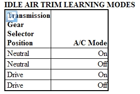
Resetting Keep-Alive Memory (KAM) 1. Resetting KAM will return PCM memory to its default setting. If not using a scan tool, disconnect negative battery terminal for a minimum for 5 minutes then go to next step. If using New Generation Star (NGS) scan tool, turn ignition on. Select ACTIVE COMMAND MODES, then RESET KEEP ALIVE MEMORY. Go to next step. 2. After KAM has been reset, engine must idle for 15 minutes to learn new idle air trim values. Idle quality will improve as strategy adapts. Adaptation occurs in 4 separate modes with engine idling, transmission selector and A/C in specified position. See IDLE AIR TRIM LEARNING MODES table.
Tuesday, July 20th, 2010 AT 2:48 PM