You need to get a copy of the manufacturer's service manual. There will be circuit descriptions that explain how each one works. The crankshaft position sensor does not put out 5.0 volts. 5.0 volts is the supply that comes from the Engine Computer to run the sensor. That same 5.0 volts also feeds the distributor pickup coil, (camshaft position sensor). If you are missing that 5.0 volts with the ignition switch on, one of those sensors is shorted. Unplug them, one at a time, but the computer will not turn the 5.0 volts back on until you turn the ignition switch off, then back on to reset it. It had it turned off to protect it.
Once those sensors have ground and 5.0 volts, they generate square wave pulses when the engine is rotating. You can't measure that signal accurately with a digital volt / ohm meter. There's a much easier test though. It's when those two signals show up at the Engine Computer that the computer turns on the automatic shutdown (ASD) relay. That relay turns on the 12 volts that feeds the ignition coil, injectors, alternator field, oxygen sensor heaters, and the fuel pump or the fuel pump relay. The easiest thing to do is to measure the voltage feeding the ignition coil or any of the injectors. All seven items will have the same color wire which is usually dark green / orange. The secret is though, there will be 0.0 volts there until the engine is being cranked. If you stick a test light or voltmeter probe in one of those places, you should see 12 volts for only one second when you turn on the ignition switch, then it will come back when you start cranking the engine. If it doesn't come back during cranking, one of those sensor signals is missing.
In your first sentence you said you "replaced the coil". You need to be specific when it comes to those details. Do you mean the ignition coil or the distributor pickup coil? If it was the ignition coil, and you had tested for that 12 volts during cranking and found it missing, you would have known to not waste your time with that. You would have known that the ignition coil along with all the injectors and fuel pump weren't being turned on.
It's important to know too if the fuel pump is running during cranking. Less than one percent of "crank-but-no-starts" are caused by anything in the ignition system, including the Engine Computer, so those things should be the last things on the list of suspects. Next, only perhaps five percent of those no-starts are caused by the fuel pump and supply system. Way too many people get hung up on the first thing they find missing, which is usually fuel pressure, and they forget or don't know to check for spark.
By far almost all crank-but-no-starts are caused by what both systems have in common, and that is those two sensors. Also, part of your dandy description included one of the most common symptoms. Both of those sensor commonly fail by becoming heat-sensitive, then they work again when they cool down for an hour. It is real common to read about an engine that runs fine until you stop for gas, then it won't restart for an hour. The engine goes through a "hot soak", meaning when it's hot but stopped so there's no air flow though the engine compartment, the heat migrates out to those sensors and makes one fail. Eventually it will fail completely, but you can fight that intermittent problem for months
Nothing logical should lead you to be thinking about grounds, but when you do, there will always be at least four ground wires on the Engine Computer, Two are "signal" grounds, and two are "power" grounds. Those terms can be misleading. No sensors and no output devices like the ignition coil and injectors are grounded on the engine. All of those ground circuits go to ground through the Engine Computer. The power grounds are for things that draw high pulses of current. That's the injectors, ignition coil, relays and solenoids. Those pulses of current will cause pulses of "voltage drops" and those would interfere with the very low-current sensor grounds. That's why the sensors have their own ground circuits independent of the high-current stuff.
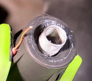
That brings me to the next point. That is trying to measure the ground wires with an ohm meter. That is as informative as saying your garden hose must be good because it's wet inside. If 19 of the 20 strands of wire were corroded off and only one tiny strand was still intact, the ohm meter would show perfect continuity, (0 ohms). You know you can't get enough current through that one wire. This is where "voltage drops" are what we use. There is no way to measure resistance in a ground wire accurately, but we can measure the RESULTS of that resistance. That is by measuring the voltage on the wire when current is trying to flow through it. That is the only way to test starter circuits too. While the engine is running, measure the voltage on the ground wire. Obviously you SHOULD have 0.0 volts but in practice you're going to find a little. Typically anything below 0.2 volts is considered okay. That's for the actual ground wires at the computer. Most of the time we're working in the sensor circuits which is on the other side of the computer circuitry. On the ground wires right on the sensors, when it comes to Chrysler systems, 0.2 volts is exactly what you must expect to find. The 0.2 volts of drop are occurring across the computer circuitry that is monitoring those circuits. That 0.2 volts tells it the proper amount of current is flowing, therefore any defect in a sensor circuit is not being caused by the ground circuit. The computer uses that information to determine which diagnostic fault code to set when it needs to do that.
It is also common to find a little more voltage drop in the power ground wires because more current is flowing through them, and current flowing through a resistance results in a drop in voltage. If all the ground circuits shared a single common wire, lets say the power circuits caused 0.5 volts to be on that wire. That would mean the sensors sharing that circuit would have 0.5 volts on their ground side. There is supposed to be 0.2 volts there. Now, if you have the throttle half way open, the voltage from the throttle position sensor should be exactly half way between 0.2 and 5.0 volts, or 2.6 volts. With 0.5 volts on the TPS ground wire, you'd have a little over 2.7 volts on the signal wire. That 0.1 volt difference may not sound like a lot, but to the MAP sensor, that is a huge difference in intake manifold vacuum which calls for a big increase in the amount of fuel being requested from the injectors. Add to that, the 0.5 volts will be pulsing up and down in time with the current pulses from the ignition coil and injectors, and that will make all the sensor voltages pulse up and down.
Most people understand the throttle position sensor measures throttle position, but they aren't aware it also tells the computer when it's at idle, when it's at wide-open-throttle, and more importantly, rate of throttle change and direction of throttle change. Sharing common ground wires would result in the computer thinking your were tapping the accelerator pedal up and down hundreds of times per minute, and it would calculate fuel metering accordingly.
I shared all of this to explain why there are two ground systems, power and signal grounds, but there are also two wires for each system in case one corrodes off of gets a high-resistance connection. You're going to find that bad ground wires for a Chrysler Engine Computer are extremely rare. Most problems are caused by improper previous service procedures.
You also introduced another problem by changing the Engine Computer before ruling out all the other possible causes of this problem. When the standby 12 volts is removed, as in when disconnecting the battery or letting it run dead, or disconnecting the computer, it loses its memory. Fuel trim numbers will have to be relearned when you start driving again. You won't even notice that taking place, but it also has to relearn "minimum throttle". Until that is done, the computer won't know when it has to be in control of idle speed. The common complaints are the engine won't start and run unless you hold the accelerator pedal down � ", you won't get the nice "idle flare-up" to 1500 rpm when you start the engine, and it will tend to stall when approaching a stop sign.
To meet the conditions for that relearn to take place, drive at highway speed with the engine warmed up, then coast for at least seven seconds without touching the pedals.
SPONSORED LINKS
Monday, June 8th, 2015 AT 10:47 PM