Try the following first.
ENTERING/EXITING SELF-DIAGNOSTICS
1. To enter self-diagnostic mode, turn ignition off. Without starting engine, turn ignition on. Press vent button on A/C-heater control panel for at least 5 seconds. If engine starts, press vent button within 10 seconds after engine has started.
2. There are 5 SELF-DIAGNOSIS STEPS and one AUXILIARY MECHANISM TEST. The AUXILIARY MECHANISM TEST checks the temperature setting trimmer. If diagnostics are entered without engine running, SELF-DIAGNOSIS STEP 4 and SELF-DIAGNOSTIC STEP 5 cannot be completed.
3. To move from one diagnostic step to another, rotate temperature switch. To move from SELF-DIAGNOSIS STEP 5 to AUXILIARY MECHANISM TEST, press fan switch. On all models, to exit self-diagnostics, press AUTO button or turn ignition off.
NOTE:
Perform SELF-DIAGNOSIS STEP 1 before proceeding to any
test to ensure that LEDs and segments illuminate, to help prevent misdiagnosis.
SELF-DIAGNOSIS STEP 1
Checks LEDs & Segments
To perform LED and segment check, set temperature switch to position "A". See Fig. 1 or Fig. 7. Repair or replace if necessary.
SELF-DIAGNOSIS STEP 2
Checks Sensor Circuits For Open/Short Circuits
1. With system in SELF-DIAGNOSIS STEP 1, set temperature switch to position "B" to enter SELF-DIAGNOSIS STEP 2. Fluorescent display will illuminate a "2". If all sensor circuits are okay, display will change to "20" after approximately 4 seconds.
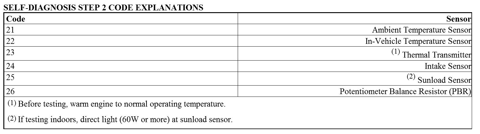
2. If a sensor circuit is faulty, circuit code number will flash on display. Shorted circuit will have a flashing "-" in front of the number 2. Open circuit will NOT have a flashing "-". For example, if number "21" is displayed on A/C-heater control panel ("2" will stay lit, and "1" will flash on and off), an open circuit is indicated.
3. If 2 sensor circuits are faulty, each code number will flash twice. To interpret codes, see SELF-DIAGNOSIS STEP 2 CODE EXPLANATIONS table.
SELF-DIAGNOSIS STEP 3
Checks Mode Door Position
1. With system in SELF-DIAGNOSIS STEP 2, set temperature switch to position "C" to enter SELF-DIAGNOSIS STEP 3. Fluorescent display will illuminate a "3". If all doors are in good order, display will change to "30" after approximately 20 seconds.
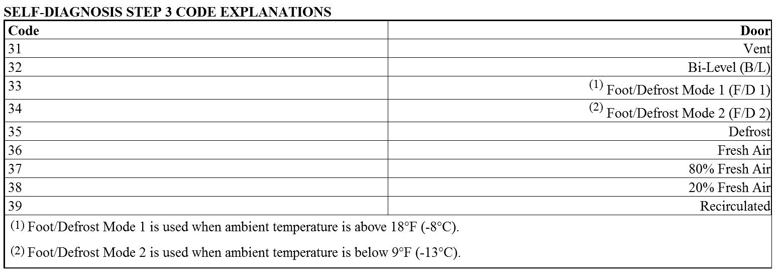
2. If a door is faulty, it will be identified by another number illuminated to the right of "3". If 2 doors are faulty, each code number will blink twice. To interpret codes, see SELF-DIAGNOSIS STEP 3 CODE EXPLANATIONS table.
NOTE:
If any mode door motor position switch is malfunctioning, mode door motor also will malfunction.
SELF-DIAGNOSIS STEP 4
Checks Operation Of Each Actuator
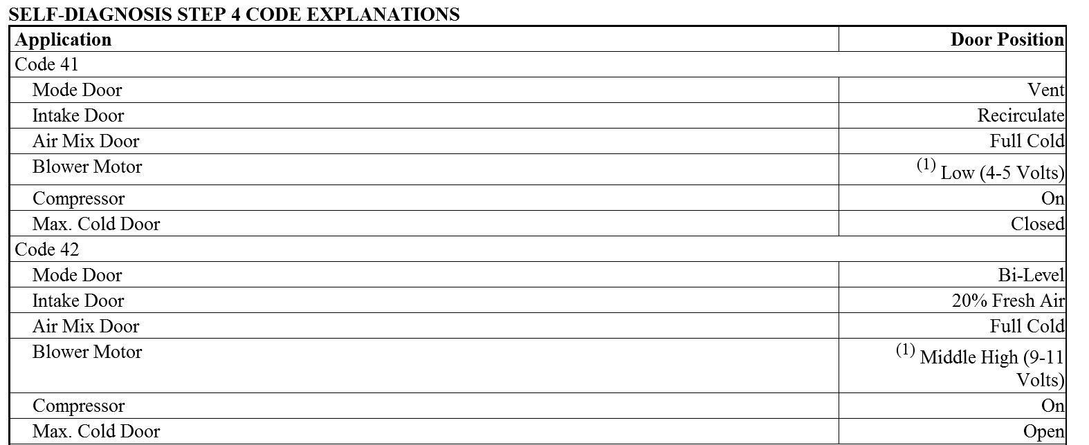
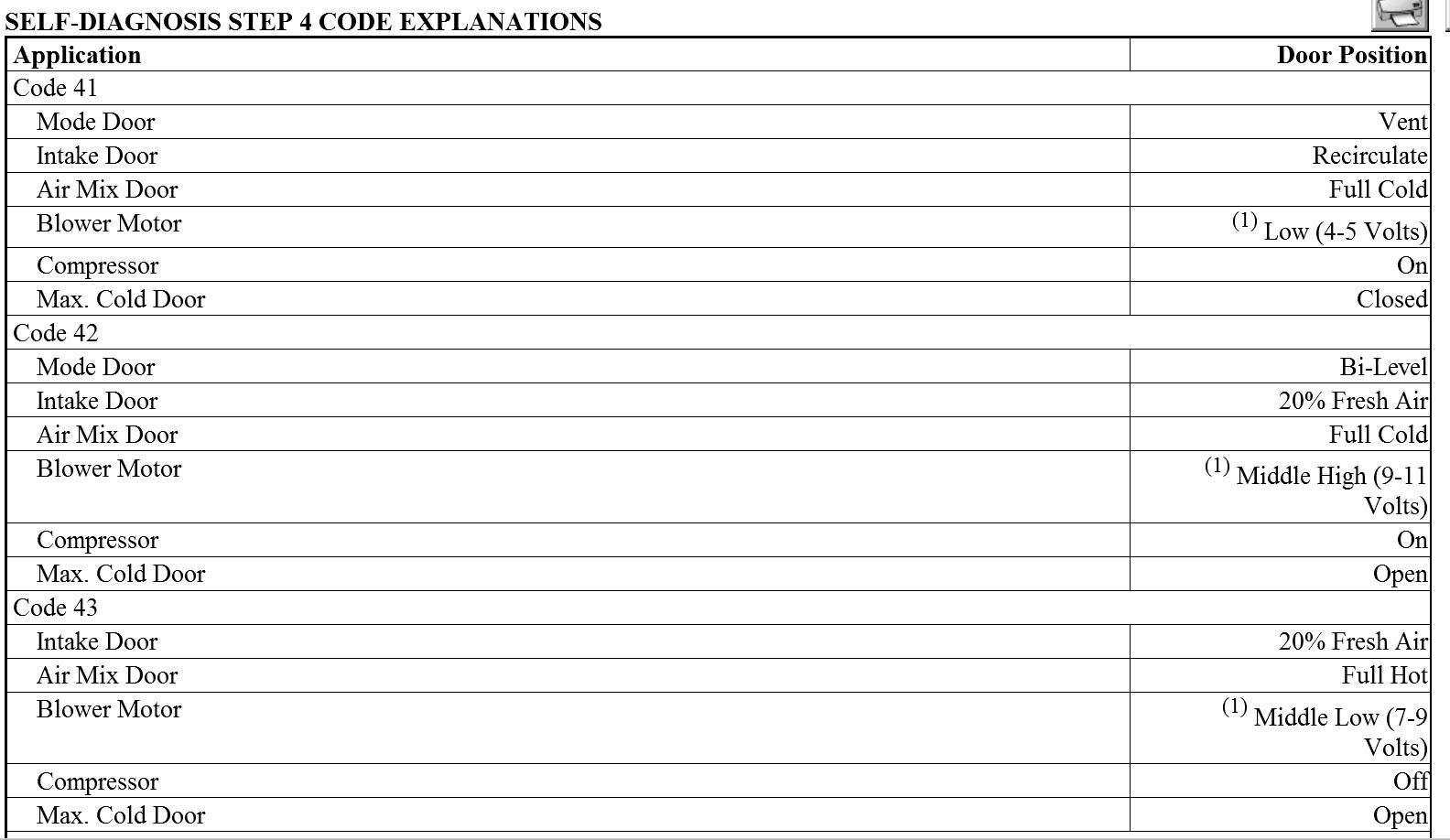
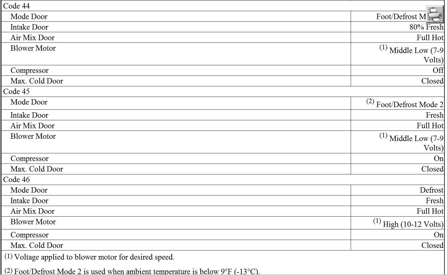
1. With system in SELF-DIAGNOSIS STEP 3, set temperature switch to position "D" to enter SELF-DIAGNOSIS STEP 4. Fluorescent display will illuminate a "41". Each time defrost button is pressed, fluorescent display to right of "4" will advance one number, up to "46".
2. After "46", the numbers begin again at "41". As numbers advance, the
commands will change air intake and outlet routes. A visual and physical
inspection must be made to ensure doors are switching properly. To determine proper door positions for each code, see SELF-DIAGNOSIS STEP 4 CODE EXPLANATIONS table.
Images (Click to make bigger)
Thursday, February 28th, 2013 AT 12:58 PM