Evaporation thermoswitch located

Tiny
ERIKSEN
  • MEMBER
  • 1995 SUBARU IMPREZA
  • 30,000 MILES
Where is the Evaporation thermoswitch located so I can
check for the earth that comes from there and goes to the AC
relay that switches the relay.
Tuesday, January 24th, 2012 AT 8:02 AM

27 Replies

Tiny
RIVERMIKERAT
  • MECHANIC
  • 6,110 POSTS
Behind the right side of the dash.
Was this
answer
helpful?
Yes
No
Tuesday, January 24th, 2012 AT 8:32 AM
Tiny
WRENCHTECH
  • MECHANIC
  • 20,757 POSTS
It will likely have a probe sensor that inserts right into the evaporator but the electronic portion should be on the outside of the case.
Was this
answer
helpful?
Yes
No
+1
Tuesday, January 24th, 2012 AT 11:02 AM
Tiny
ERIKSEN
  • MEMBER
  • 13 POSTS
Bith incorrect. It is a RHD car so in the passenger side footwell is the plug.

Damn ourput no good to pull in AC relay
Was this
answer
helpful?
Yes
No
Tuesday, January 24th, 2012 AT 11:20 AM
Tiny
ERIKSEN
  • MEMBER
  • 13 POSTS
Its in the passenger footwell!

Geez, I should be on this site.

Now the question is what is the reading on the 3 wires in the plug connected?

The white

The red

The Brown
Was this
answer
helpful?
Yes
No
+1
Tuesday, January 24th, 2012 AT 11:24 AM
Tiny
WRENCHTECH
  • MECHANIC
  • 20,757 POSTS
Oh really.
The sensor by design has to read evaporator temperature so you tell me how it does that without being at the evaporator.
Was this
answer
helpful?
Yes
No
Tuesday, January 24th, 2012 AT 11:24 AM
Tiny
ERIKSEN
  • MEMBER
  • 13 POSTS
You are correct, it is in there, but directly outside is the plug I was looking for ant the concern is that no earth on the white that woulds pull in the AC relay.
Was this
answer
helpful?
Yes
No
Tuesday, January 24th, 2012 AT 11:37 AM
Tiny
RIVERMIKERAT
  • MECHANIC
  • 6,110 POSTS
Wrenchtech, right hand drive. So everything is backwards. We'd have known that if told the vehicle was a UK model. I should have known seeing the word 'earth' instead of 'ground'.

Our reference shows different colors, but here goes:
Green/Red=12V when on. I'm going to think that's your Brown.
Brown/White=Ground. Your White.
Red/Black=12V when ignition on. Your Red.

I've uploaded a copy of the schematic we have.
Was this
answer
helpful?
Yes
No
-1
Tuesday, January 24th, 2012 AT 7:42 PM
Tiny
ERIKSEN
  • MEMBER
  • 13 POSTS
Thanks for the effort and reply but the "issue" of this story is the
Evaporation thermoswitch not pulling in the AC relay.
BrR (Brown / Red) 12v - Easy to trace.

White - MM (multimeter) Goes to the AC relay pullin coil and should be lesser potential difference than the BrY (Brown / Yellow)end of the pullin coil as the BrY has 12v when AC switch is turned on and you can trace it through the pressure switch where it changes to GY (Green / Yellow) the to the switch.

Thats straightforward and confirmed but the RED wire which looks like it feeds a signal to the amp in the Evaporation thermoswitch
seems to be the problem. When I measure the voltage with everything running it says 12 v, so how is the white cable supposed to have -ve voltage? And tracing the red cable you see it goes back to earth via Diode i17 and the fan switch.

So logic says its the diode. Will try finding it today, great fun in the sweaty humid weather here in Phuket, will also measure my friends Evaporation thermoswitch now that I found the connector. (Just ran my hand up under near the glove box a bit to the side and there it was.

Thanks for all the suggestions, any info on the Evaporation thermoswitch "AMP" would be helpful as I am just guessing how that works. In that I mean, it cycles the AC so it wont freeze up right? (So cant bypass it)

Also, the temp adjust switch (how cold you want it switch), I see it simply has a mechanical cable that moves a flap like something in the footwell. How does it adjust for compressor time engagement? Must have electrical cables as well, but I cant see any.
Thanks
Was this
answer
helpful?
Yes
No
Tuesday, January 24th, 2012 AT 11:51 PM
Tiny
WRENCHTECH
  • MECHANIC
  • 20,757 POSTS
The thermoswitch is a solid state transister that applies trigger ground to the relay to activate it.
Was this
answer
helpful?
Yes
No
+1
Wednesday, January 25th, 2012 AT 2:42 AM
Tiny
WRENCHTECH
  • MECHANIC
  • 20,757 POSTS
Apparently my answers aren't showing up.
Was this
answer
helpful?
Yes
No
Wednesday, January 25th, 2012 AT 2:44 AM
Tiny
RIVERMIKERAT
  • MECHANIC
  • 6,110 POSTS
None of our answers were showing up properly earlier today, Wrenchtech.
Was this
answer
helpful?
Yes
No
Wednesday, January 25th, 2012 AT 4:33 AM
Tiny
RIVERMIKERAT
  • MECHANIC
  • 6,110 POSTS
Methinks the system has another glitch. I've been notified of four updates since my last reply. Over the past 3 hours.
Was this
answer
helpful?
Yes
No
Wednesday, January 25th, 2012 AT 6:35 AM
Tiny
ERIKSEN
  • MEMBER
  • 13 POSTS
Now this is the first useful info, it simply turns it on and off at set temps. How basic. Not impressed with the design, in this day and age with fuel consunption and effeciency one would think one could set desired temp to be met. Everyones different.
So I MM my friends car today, got logical readings and am now more sure the diode is blown as I thought, so now need to find a 2nd hand one cut off and I splice it in, but another problem is now there, when I hard wire and earth on the red, I get compressor chatter. I suspect weak 12v supply bypasses at the relays. Will test more tomorrow. Is 7pm now here in the land of ladies and plonk. You guys just waking up. If you guys ever come to phuket let us know. Continue in my tomorow, thanks all
Was this
answer
helpful?
Yes
No
Wednesday, January 25th, 2012 AT 12:04 PM
Tiny
WRENCHTECH
  • MECHANIC
  • 20,757 POSTS
If you want a system to control temp settings, then you have to buy a car that is equipped with auto temp control system. The particular sensor is there for the sole purpose of preventing the evap from freezing up and in turn taking out the compressor from lack of lubrication.
Was this
answer
helpful?
Yes
No
Wednesday, January 25th, 2012 AT 12:15 PM
Tiny
RIVERMIKERAT
  • MECHANIC
  • 6,110 POSTS
Been to the PI, eriksen. Cleaner than Phuket. Had fun, wasn't impressed.
Was this
answer
helpful?
Yes
No
Wednesday, January 25th, 2012 AT 7:23 PM
Tiny
ERIKSEN
  • MEMBER
  • 13 POSTS
Hi guys, nearly there now. Looking at Wrenchtech's posting and that made me think a bit deeper.
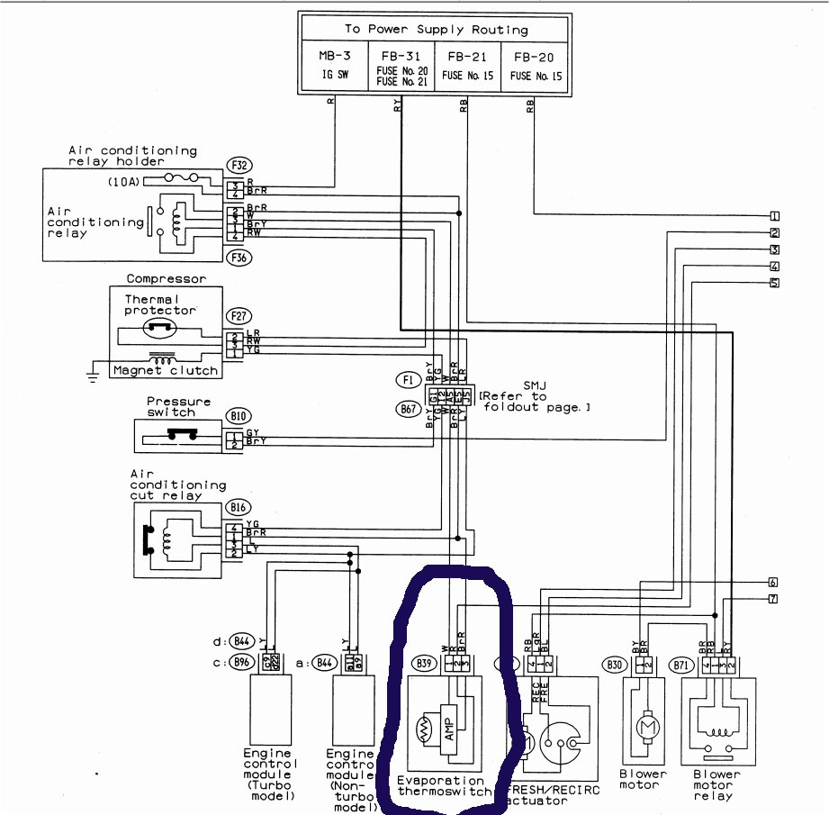
Thermoswitch -
I MM my friends car that can't be started (ignition only) but that should not matter as the temp is HOT in there, and sure enough, he gets an earth on the white wire earth that pulls in the A/C relay
On mine -
When I apply an earth to the white wire the A/C turns on. Fine.
So the problem is either in the "thermoswitch" or could it be the temp sensor itself?

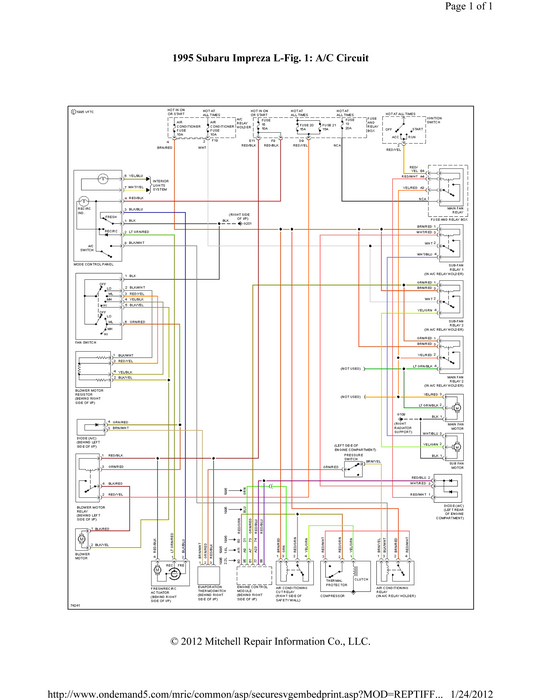
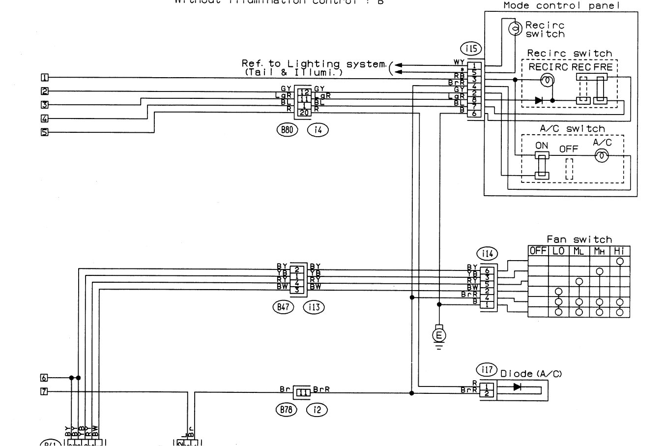
What part exactly is faulty here? I cannot find any circuit diagrams of inside to help. I was thinking of testing between the connector/switch/diode/transitor and the evaporator unit, they have a foot or so long cable with 2 wires inside. I take it this is a simple temp sender unit that varies the resistance output to the comparitor as shown in Wrenchtech's schematic as above?

The reason why I am wanting to isolate the fault is because they are a bit "odd" over here, I could probably get one cut and sent to me, but if it includes the evaporator unit and the sensor then "bigbox"="big money"

So guys, what resistance reading should be on the evaporator unit's temp sensor? I can cut the twin cable output and measure it.
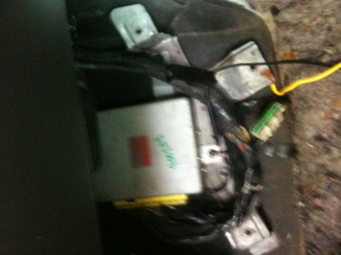
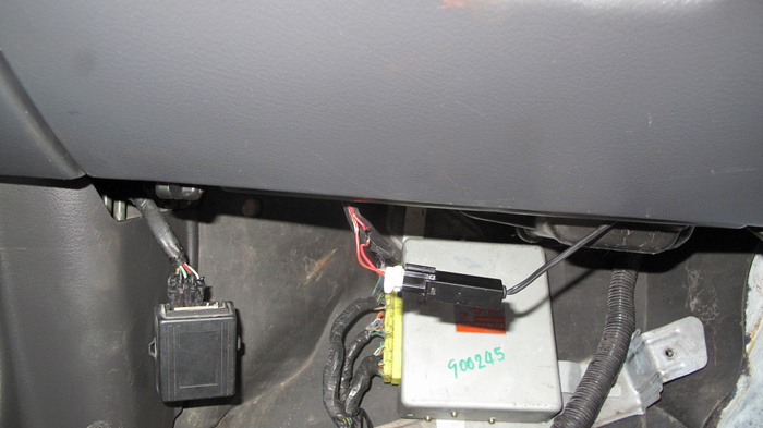
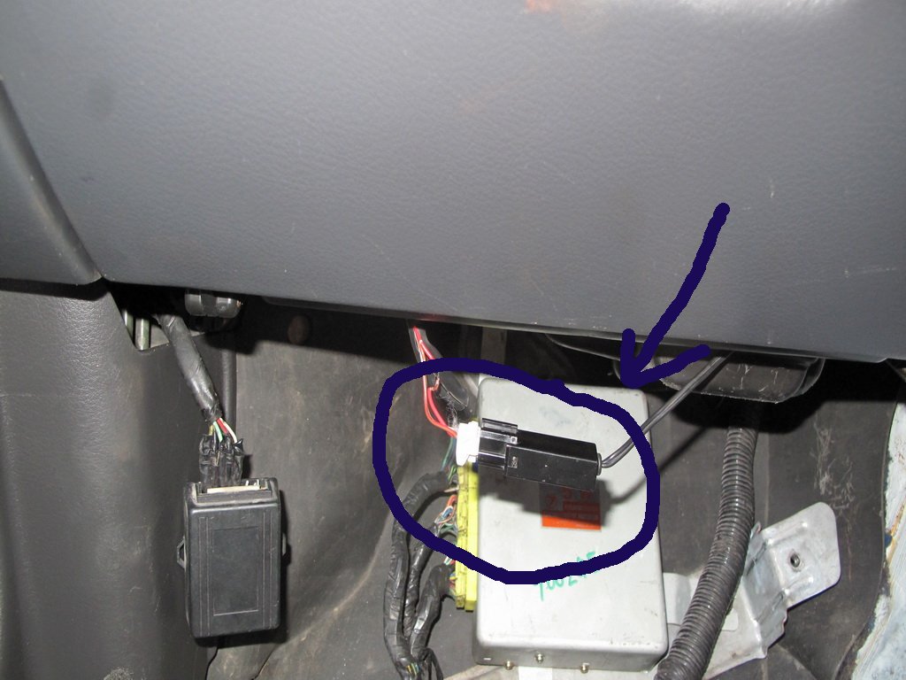
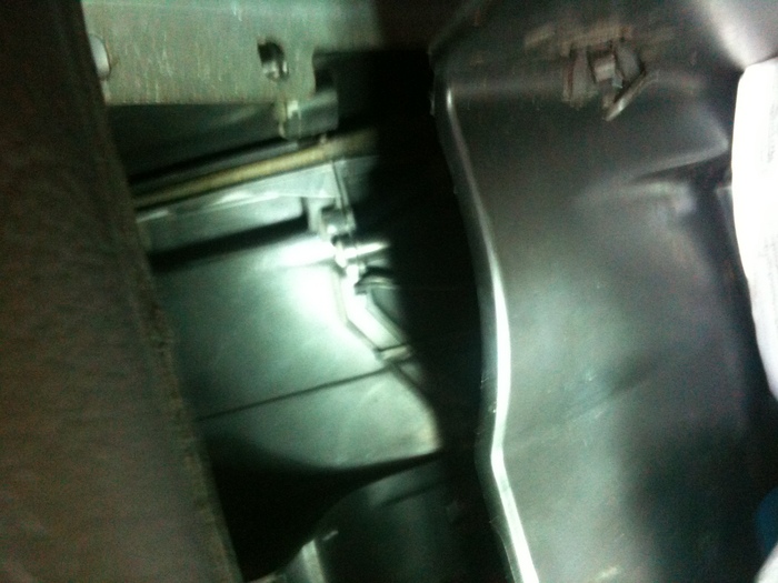
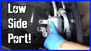
See the attached picture please, excuse the blurry one, that's the culprit, you guys probably seen it heaps. Then see the twincore cable going to the evap box.

Perhaps I should just pull it all apart, it's most likely never been cleaned. No such thing as preventative maintenance over here. Just so damn hot. Ok for drinking cold beer under a tree at the beach but not for working. One guy I know here wants to put A/C in his shed, lol.
Have a great day and thanks for your expertise.
Regards,

Erik (From Australia)
Was this
answer
helpful?
Yes
No
Thursday, January 26th, 2012 AT 6:49 AM
Tiny
ERIKSEN
  • MEMBER
  • 13 POSTS
Took a better pic. Sorry about that.

Thanks.
Was this
answer
helpful?
Yes
No
Thursday, January 26th, 2012 AT 6:58 AM
Tiny
ERIKSEN
  • MEMBER
  • 13 POSTS
Guess I should just cut that twin core cable and see what resistance reading I get there. Do you guys know what the reading would be?
If its open then I would say the temp sender is kaput.
Was this
answer
helpful?
Yes
No
Thursday, January 26th, 2012 AT 7:15 AM
Tiny
RIVERMIKERAT
  • MECHANIC
  • 6,110 POSTS
I presume you're talking about the connection with the white connector and the red wires? You should be able to probe it with your meter leads.

Also, you should be able to locate specs for the thermistor online. I looked through our reference for about 30 minutes and that item is one of the few I couldn't find specs for.
Was this
answer
helpful?
Yes
No
Thursday, January 26th, 2012 AT 8:06 AM
Tiny
ERIKSEN
  • MEMBER
  • 13 POSTS
Thanks for your reply.
You posted this before so we have different colors for some reason, but my diagrams mostly match my car.

Our reference shows different colors, but here goes:
Green/Red=12V when on. I'm going to think that's your Brown.
Brown/White=Ground. Your White.
Red/Black=12V when ignition on. Your Red.

No, you cant measure like that, need to measure on the other side, the twin core cable coming from the temp sensor, see pics please.
Any idea what a healthy temp sensor resistance reading would be?
And whats ur thoughts on pulling it all out for the big 15 year clean anyways? Is it hard?
Thanks,

Erik.
Was this
answer
helpful?
Yes
No
Thursday, January 26th, 2012 AT 8:19 AM

Please login or register to post a reply.

Sponsored links