DISABLING & ACTIVATING SRS SYSTEM
WARNING: Wait about 15 seconds after disabling air bag system. The DERM maintains system voltage for about 15 seconds after battery is
disconnected. Servicing air bag system before 15 seconds may cause accidental air bag deployment, possibly causing personal injury.
DISABLING SRS SYSTEM
NOTE: When disconnected, the air bag connector is automatically shorted.
Turn ignition switch to "LOCK" and remove key. Remove SRS fuse C-21, C-22, C-23 and C-24 from left dash side of lower fuse block or disconnect battery. Disconnect Yellow 3-way connector at the base of steering column. Remove glove box assembly. Disconnect Yellow 4-way connector behind glove box assembly. See Fig. 1.
ACTIVATING SRS SYSTEM
Turn ignition switch to "LOCK" and remove the key. Connect Yellow 4-way connector passenger-side air bag module. Install glovebox. Connect Yellow 3-way connector at the base of steering column. Install SRS fuse C-21, C-22, C-23 and C-24 to left dash side lower fuse block or reconnect battery. Turn ignition switch to "ON" and verify that "AIR BAG" warning lamp flashes seven times and then turns off. If it does not operate as described, see DIAGNOSTIC PROCEDURES.
STEERING WHEEL
WARNING: To avoid injury from accidental air bag deployment, read and
carefully follow all WARNINGS and SERVICE PRECAUTIONS.
Removal
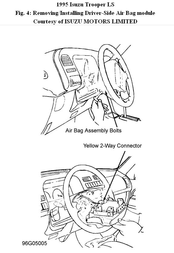
1. Disable the air bag system. See DISABLING SRS SYSTEM. Loosen air bag module fixing bolts from behind steering wheel assembly using Torx driver until air bag module can be released from steering wheel.
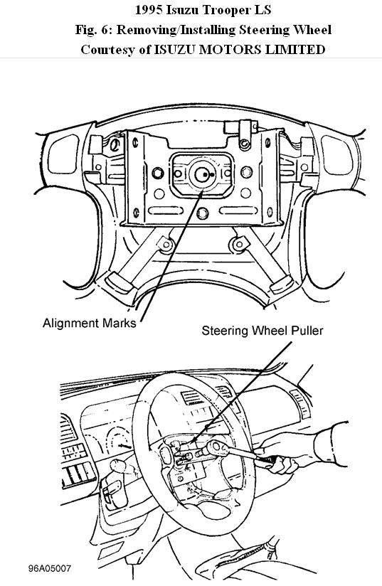
2. Disconnect Yellow 2-way connector located behind air bag module and remove air bag module. Disconnect horn lead connector. Remove steering wheel attachment nut. Apply a setting mark across steering wheel and shaft so parts can be reassembled in original position. See Fig. 6.
3. Turn wheels to straight ahead position before removing steering wheel and remove wheel using tool J-29752. Feed wiring through wheel and remove wheel.
CAUTION:Never apply force to steering wheel in direction of shaft by using hammer or impact tools. The steering shaft is designed as an energy absorbing unit and may collapse.
Installation
1. Install steering wheel and align the setting marks. Reverse removal procedure. Tighten steering wheel fixing nut to 25 FOOT lbs. (34 N.M). Tighten Torx bolts to 69 INCH lbs. (8 N.M). Activate air bag system. See ACTIVATING SRS SYSTEM.
SRS COIL ASSEMBLY
WARNING: To avoid injury from accidental air bag deployment, read and
carefully follow all WARNINGS and SERVICE PRECAUTIONS.
Removal
1. Disable the air bag system. See DISABLING SRS SYSTEM. Loosen air bag module fixing bolts from behind steering wheel assembly using Torx driver until air bag module can be released from steering wheel.
2. Disconnect Yellow 2-way connector located behind air bag module and remove air bag module. Disconnect horn lead connector. Remove steering wheel as previously described.
3. Remove steering lower cover and engine hood opening lever. Remove driver knee bolster assembly. Remove steering column cover. Remove air conditioning lower duct and disconnect 3-way wiring harness connectors located at base of steering column. Remove combination switch assembly with SRS coil.
NOTE:
SRS coil is part of combination switch assembly and cannot be
replaced separately. Be sure not to remove SRS coil from combination switch assembly.
Installation
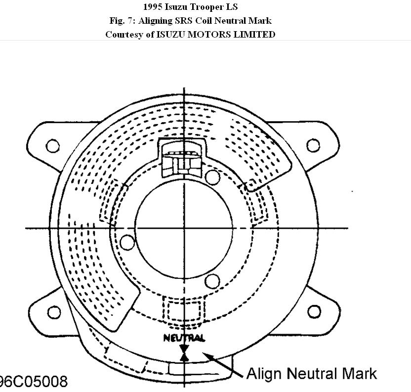
1. To install, reverse removal procedure turning SRS coil clockwise to full, return about 3 turns and align the neutral mark. See Fig. 7.
2. Activate air bag system. See ACTIVATING SRS SYSTEM.
CAUTION:When turning SRS coil clockwise to full, stop turning if resistance is felt. Forced turning may damage cable in SRS coil.
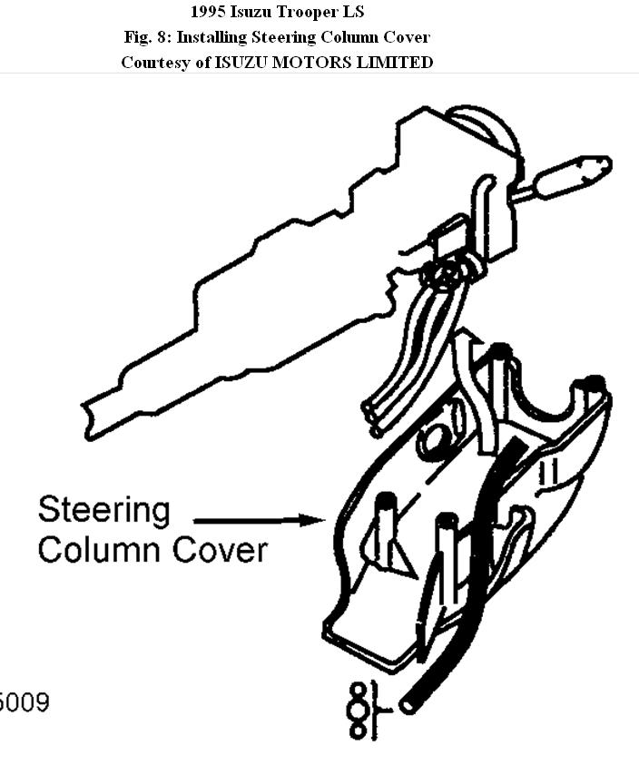
CAUTION:When installing steering column cover, be sure to wire (through each harness) so that harness starter switch, combination switch, and SRS coil will not catch wiring. See Fig. 8.
IGNITION SWITCH/COLUMN LOCK ASSEMBLY
Removal
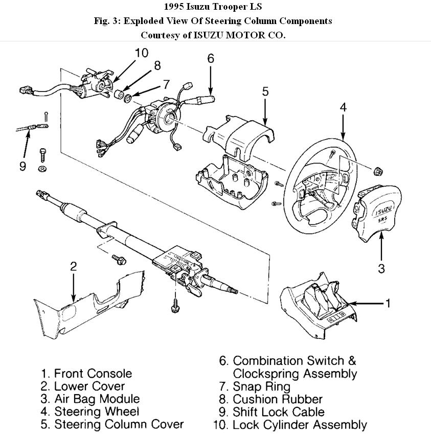
1. Disconnect negative battery cable. Remove horn pad and steering wheel. See STEERING WHEEL & HORN PAD. Remove lower instrument panel and steering column shrouds. See Fig. 3. Remove combination switch. Disconnect shift lock cable (A/T only). Disconnect ignition switch wiring connectors located behind lower instrument panel. Remove tie-straps retaining harness to column.
2. If ignition switch/column lock assembly's shear bolt-stud heads are accessible, use a hacksaw to cut a slot into exposed head of studs. Using a blade screwdriver, remove studs. If ignition switch clamp shear bolt-stud heads are not accessible, remove steering column
from instrument panel to access bolt-stud heads.
3. If shear bolt-stud heads are recessed or hard to reach with a hacksaw, lightly center punch bolt-stud heads. Use drill bit and screw extractor to remove studs. Remove ignition switch/column lock assembly.
Installation
1. To install, reverse removal procedure. Install NEW shear bolts and finger tighten temporarily. Ensure proper operation of steering lock and ignition switch mechanism.
2. With ignition switch in LOCK position, tighten shear bolts until heads break off. Connect ignition switch wiring connector. Install combination switch (if removed) and tie-strap harnesses to column. Install upper and lower steering column shrouds, steering wheel and horn pad. Tighten all bolts to specification.
Images (Click to make bigger)
SPONSORED LINKS
Thursday, December 2nd, 2010 AT 1:47 PM