Need help testing my ignition

Tiny
LRHOGGARD
  • MEMBER
  • 1995 ACURA INTEGRA
  • 230,000 MILES
There is information about testing most ignition components but I have not seen anything posted about testing the pick up coil. Intermittent starting problems began months ago after a 5 to 30 min stop in warm weather. Best start when problem occurred was to wait or use flooded engine start procedure. Check engine light would come on intermittently after start up and go out after next start up. Suspected faulty thermostat or temp sensor creating an improper temp signal and faulty fuel mixture.

Last time problem occurred engine would not start, towed it home and used your troubleshooting procedure for ignition system. All good so replaced ignitor, no help.

Only variance from test steps is the resistance of the ignition coil secondary circuit. At 50 degrees it reads 10,800 ohms. Probably close enough to spec or even correct at that ambient temp.

Check engine light goes out after 2-3 seconds and ECU smells good. I noticed there is no test for the ignition pick up coil. I assume there should be an AC voltage signal during starter engagement? What are the specs? Distributor shaft is turning.

One more thing that should not matter but will mention it. I piggy backed new ignitor in with a ground lead from metal mounting bracket to battery instead of installing it into distributor.

Any suggestions will be appreciated.

Thank you.
Sunday, November 13th, 2011 AT 10:08 PM

5 Replies

Tiny
RASMATAZ
  • MECHANIC
  • 75,992 POSTS
Scan the computer for code/s and get back if any present, this is your starting point-
Was this
answer
helpful?
Yes
No
Sunday, November 13th, 2011 AT 10:13 PM
Tiny
LRHOGGARD
  • MEMBER
  • 3 POSTS
This appears to be an OBD I system. Located green rubber connector holder under glove box. Removed two multi-connectors from holder and jumped the two wire connector. When key was turned to the engine on position the ABS light flashed 4-4, 4-8, and 4-8. Is this correct method to retrieve ECU codes? Seems odd that one code was repeated. So does this represent code 44, 48, 48, or 4, 8, 8? Or do I need to jumper other wires for ECU codes?

Do you have specs for testing the ignition pick up coil?
Was this
answer
helpful?
Yes
No
Monday, November 14th, 2011 AT 5:03 PM
Tiny
KHLOW2008
  • MECHANIC
  • 41,815 POSTS
For the intermittent non starting, remov the PGM-FI main relay and check the circuit board. Resolder the circuit board and retest. A known fault with the relay which can be rectified by resoldering. If you want it to last, replace all the solder with a higher quality solder.

You did it correctly. If there is any code with the engine computer, the Check Engine Light is the one that would flash.

Does the ABS indicator light stay on when driving?

The diagram shows how to retrieve the trouble codes. Similar procedure for checking CEL codes.

Reconfirm the ABS codes and let me know what they are.
Was this
answer
helpful?
Yes
No
Tuesday, November 15th, 2011 AT 1:54 PM
Tiny
LRHOGGARD
  • MEMBER
  • 3 POSTS
This is a NO START and NO SPARK diagnostic please stay on track.

The PGM-FI main relay circuit board appears good although there is an order of burnt contacts. I think this is normal for relay contacts which carry a load? The relay powers up with key on for about 5 seconds. Considering that there is battery voltage to the ignitor and ignition coil I suspect that the PGM-FI is working? A wiring schematic of the ignition system would be most helpful.

I have asked for test spec's for the ignition Hall Effect unit in both previous messages. I assume you either do not have the specs or consider testing irrelevant.

This is a NO START and NO SPARK diagnostic please stay on track.
I will donate an additional $25.00 US for ignition schematic and related test procedures.
Was this
answer
helpful?
Yes
No
Tuesday, November 22nd, 2011 AT 6:49 PM
Tiny
KHLOW2008
  • MECHANIC
  • 41,815 POSTS
IGNITION CHECKS

ELECTRONIC IGNITION SYSTEM

Spark

1. Crank engine. Using a high output spark tester, test for a strong Blue spark at each secondary ignition plug wire. If spark is not as described, go to next step.

2. Verify resistance of each spark plug wire is not more than 25,000 ohms. Unplug and inspect all related ignition system connectors and harness. Clean or repair as necessary, and recheck spark. If strong Blue spark is still not present, go to
IGNITION COIL POWER SOURCE.

Ignition Coil Power Source

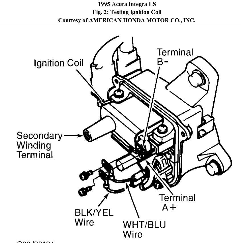
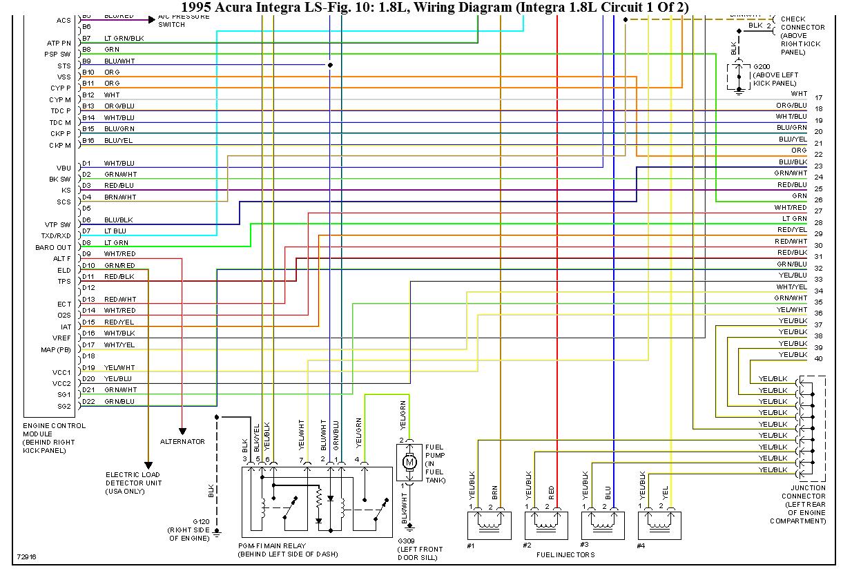
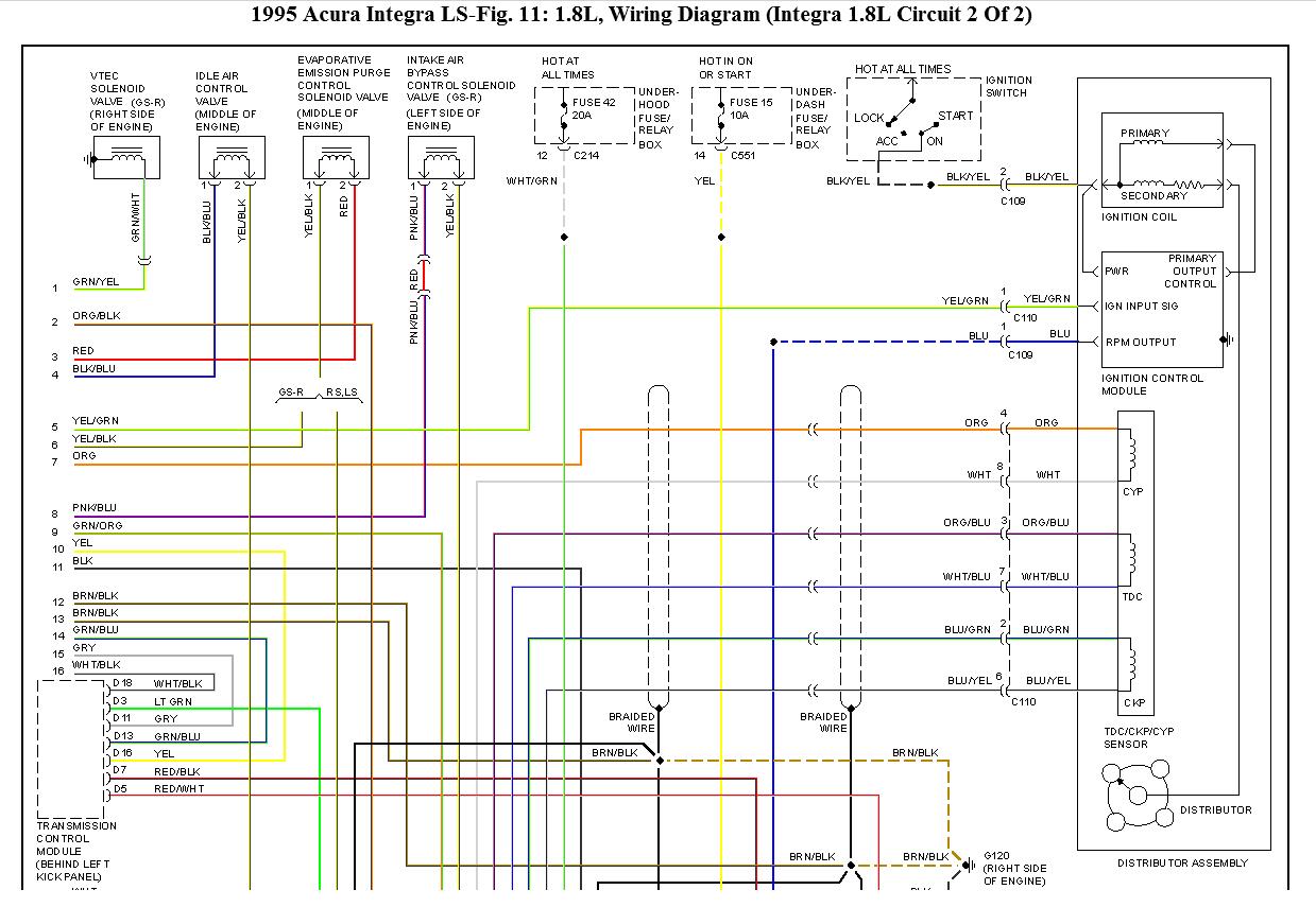
1. Remove distributor cap. Disconnect ignition coil primary leads. Turn ignition on. Measure voltage between ground and Black/Yellow wire of ignition coil wiring harness. See Fig. 2.

2. Battery voltage should exist. If battery voltage does not exist, inspect for open in Black/Yellow wire between ignition coil and ignition switch. If wire is okay, go to IGNITOR INPUT TEST procedure.

Ignitor Input Test

1. Turn ignition off. Remove distributor cap and rotor. Disconnect Black/Yellow, White/Blue, Yellow/Green, and Blue wires from igniter. Turn ignition on. Test for battery voltage between Black/Yellow wire of harness and body ground.

2. If battery voltage exists, go to next step. If battery voltage does not exist, inspect for open in Black/Yellow wire between ignition switch and igniter wiring harness connector. If battery voltage exists, inspect for voltage between White/Blue wire and body ground. If battery voltage does not exist, inspect White/Blue wire and ignition coil for open circuit.

3. Unplug PCM wiring harness connector. Inspect Yellow/Green wire for continuity between PCM wiring harness connector and igniter. Inspect Blue wire for continuity between igniter and tachometer. Repair or replace wiring as necessary. If wiring is okay, replace igniter.

Ignition Coil Test

1. Turn ignition off. Remove distributor cap. Remove screws retaining primary ignition leads. Disconnect primary leads from ignition coil. Measure resistance between primary terminals "A" and "B" on ignition coil. See Fig. 2. Resistance should be 0.6-0.8 ohm at 6 8°F (20°C).

2. Measure secondary resistance between coil terminal "A" and secondary terminal (coil tower). Resistance should be 12,800-19,200 ohms at 68°F (20°C). Replace coil if resistance is not within specifications.
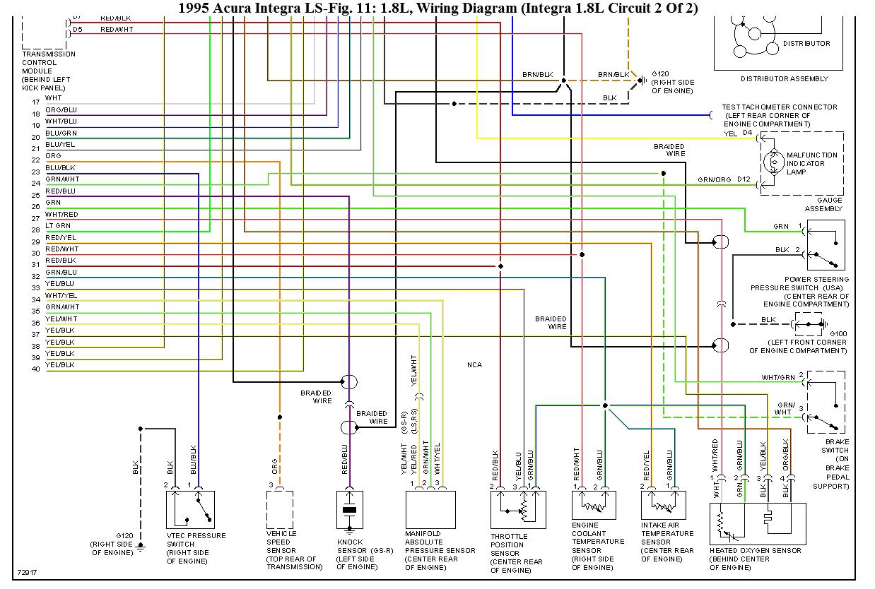
PCM Input Signals

1. Timing control and triggering of fuel injectors are based on input signals from TDC/CRANK/CYL sensors. These sensors are Permanent Magnet (PM) generator pick-up coils.

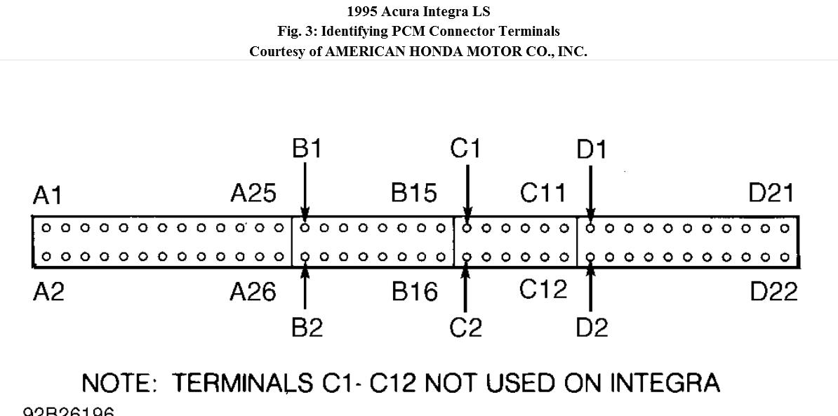
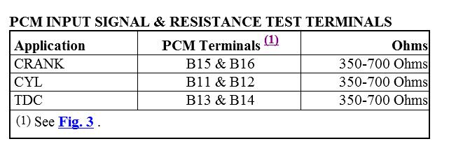
2. Using a DVOM (preferably with bar-graph function) on low-volt scale, test each sensor for pulse voltage signal at indicated PCM harness terminals while engine is cranking. See PCM INPUT SIGNAL & RESISTANCE TEST TERMINALS. If pulse signal is present, sensor is okay. If pulse signal is not present, go to next step.

3. Turn ignition off. Unplug PCM connector. Inspect wiring harness and connectors. Measure resistance of each sensor at indicated PCM harness terminals. See PCM INPUT SIGNAL & RESISTANCE TEST TERMINALS. If resistance is within specification, go to next step. If resistance is not within specification, go to step 5).

4. Test each terminal for continuity to ground. If continuity exists, unplug sensor connector, and again test appropriate PCM terminal for continuity to ground. If continuity still exists, repair short to ground in harness. If continuity does not exist, replace sensor.

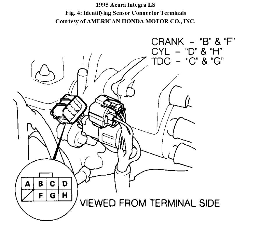
5. Unplug sensor connector. Measure resistance of sensor. See
Fig. 4. If resistance is within specification, repair open, short, or poor connection in sensor harness between PCM and sensor. See
PCM INPUT SIGNAL & RESISTANCE TEST TERMINALS. If sensor resistance is not within specification, replace sensor assembly.
Was this
answer
helpful?
Yes
No
Tuesday, November 22nd, 2011 AT 9:02 PM

Please login or register to post a reply.

Sponsored links