Automatic Locking Hubs
Hubs are engaged (locked) when transfer case is shifted into 4WD(vehicle stopped) then driven at least 4 feet in forward direction. Hubs will automatically lock. To unlock automatic hubs, stop vehicle, shift into 2H then drive at least 4 feet in reverse. Hubs will automatically unlock.
There are no actuators for the locking hub.
AUTOMATIC LOCKING HUB
Removal
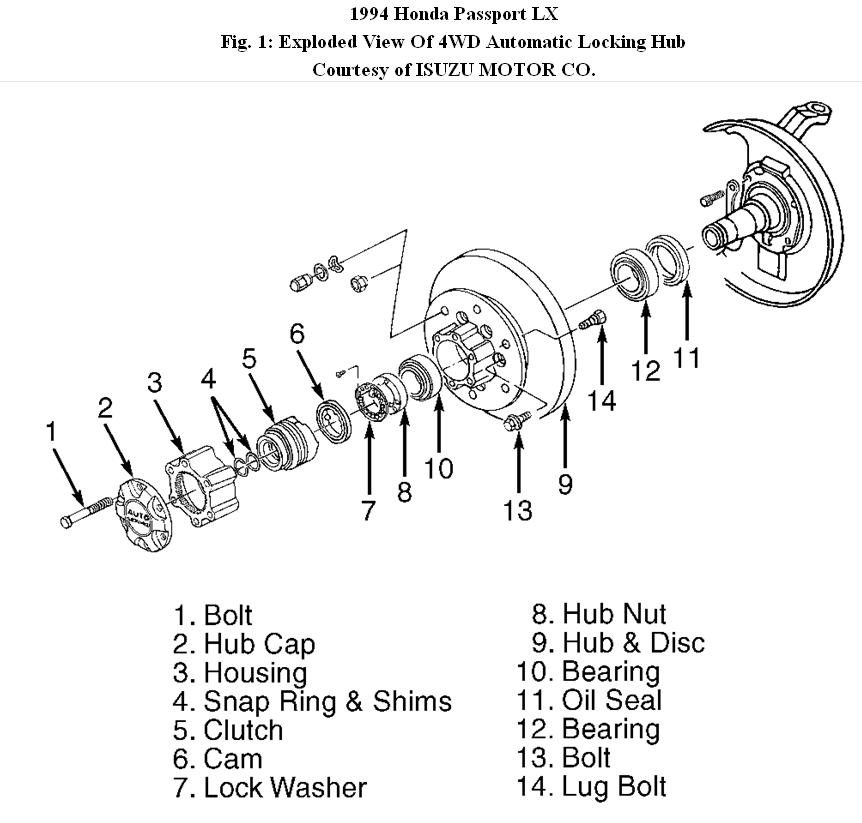
1. Place transfer case lever in 2H position. Move vehicle back and forth about 4 feet or more. Raise and support vehicle. Remove wheel and brake caliper. Wire caliper aside. Remove 6 bolts and locking hub cover and housing. See Fig. 1.
2. Remove snap ring and shims. Remove clutch assembly with inner cam. Remove lock washer. Remove hub nut with Wrench (J-36827). Remove outer bearing with hub and rotor assembly. Mark hub and rotor relation if they are to be separated.
Inspection
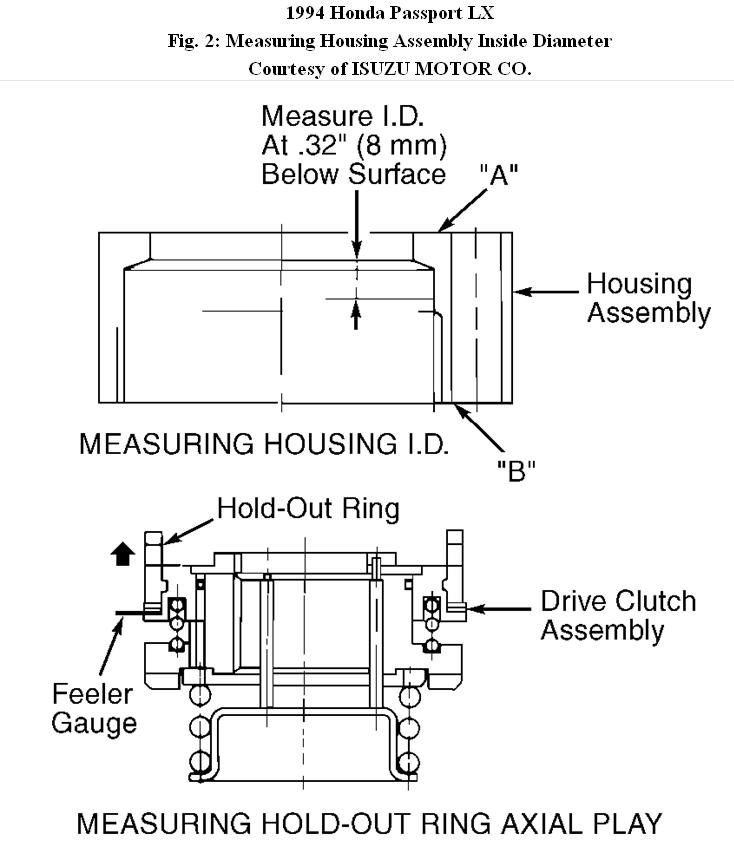
1. Measure inside diameter of housing assembly at.32" (8 mm) below "A". See Fig. 2. Inspect flange surface of "A" and "B" for excessive wear.
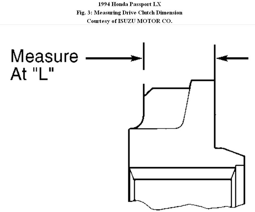
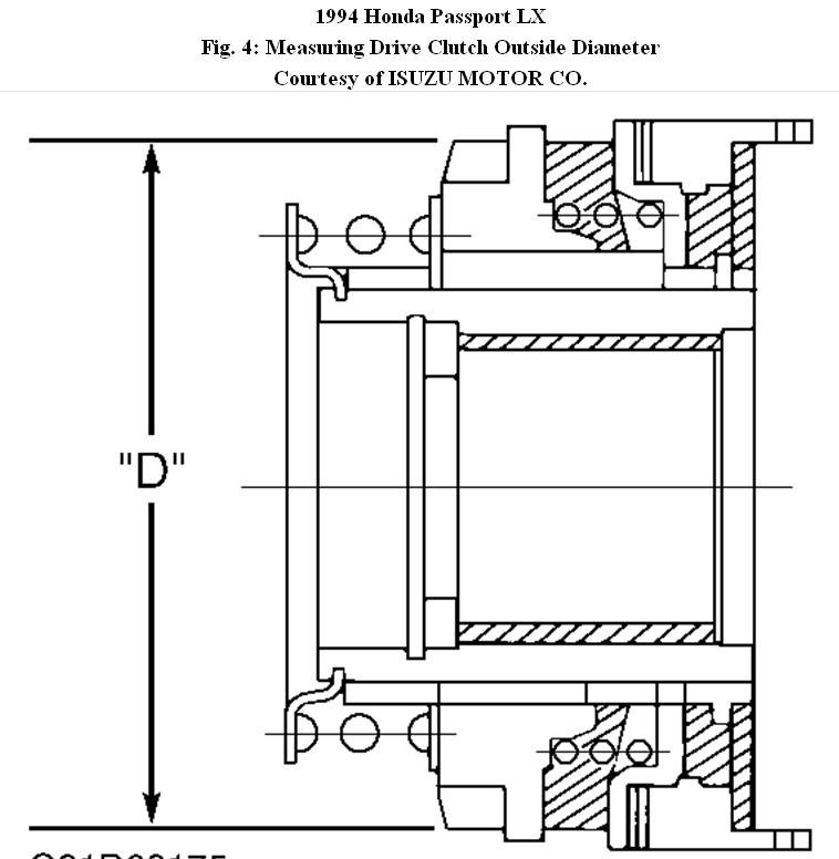
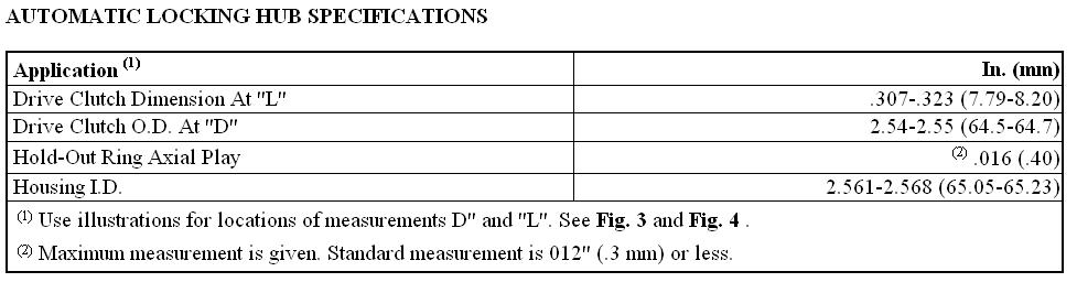
2. Using feeler gauge, measure hold-out ring axial play of drive clutch assembly. See Fig. 2. Measure drive clutch assembly at dimensions "L" and "D." See Fig. 3 and Fig. 4. Replace component if not within specification. See AUTOMATIC LOCKING HUB SPECIFICATIONS table.
Installation
1. Ensure transfer case lever is in 2H position. Ensure hub flange, lock washer and axle splines are clean. Install hub and rotor assembly with bearings. Install hub nut with chamfered edge facing outward. Tighten hub nut to specification. Install lock washer so one of the holes aligns with one of hub nut screw holes. Install lock screw.
2. Install inner cam so cam keyway aligns with spindle groove. If inner cam is difficult to install, Installer (J-38194) and a plastic hammer may be used to lightly tap inner cam to ensure it is fully seated. Ensure cam teeth face outward.
3. If new parts have been installed, determine shim thickness. To determine shim thickness, raise lower control arm with a floor jack until axle shaft is horizontal. Install Gauge (J-36836 and J-36835-2) over end of axle shaft until gauge contacts lock washer. Using feeler gauge, measure clearance between gauge and snap ring groove. If clearance exceeds.004" (.10 mm), install shims between clutch assembly and snap ring upon installation of snap ring.
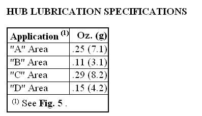
4. Remove gauge. DO NOT remove inner cam. Apply multipurpose grease to axle shaft splines. Apply grease to proper areas of drive clutch assembly and housing. See Fig. 5. Apply proper amount of grease to designated areas. See HUB LUBRICATION SPECIFICATIONS table.
5. Align cut-out area of drive clutch assembly with concave area of inner cam. Engage cam teeth of drive clutch assembly with inner cam teeth by rotating axle shaft.
CAUTION:Always install NEW snap ring on axle shaft.
6. Place snap ring installer in center hole of axle shaft. Hit snap ring installer by hand while pulling axle shaft outward. DO NOT use hammer to install snap ring. Force snap ring into position and ensure it is fully seated.
7. Apply sealer (Loctite 515) to both sides of housing assembly and flange surface of driven clutch assembly. Install housing-to-hub bolts and tighten to 43 ft. Lbs. (58 N.M). Ensure hub rotates smoothly, if so shim selection is correct. Install brake caliper and wheel. Tighten caliper bolts and wheel lug nuts to specification.
Images (Click to make bigger)
SPONSORED LINKS
Tuesday, January 11th, 2011 AT 8:00 PM