Hello. Thanks for the donation. Much appreciated
Start by having the fuel pressure checked. And check for diagnostic trouble codes stored on the cars computer !
FUEL SYSTEM - DRIVEABILITY/STARTING ISSUES - CUSTOMER COMPLAINTS - DIAGNOSTIC PROCEDURES
TECHNICAL SERVICE BULLETIN
Reference Number(s): XT310-02, Date of Issue: September, 2002
JAGUAR:2002 MY-ON X-TYPE
VIN:C00001-ON
Related Ref Number(s): XT310-02
ARTICLE BEGINNING
Issue:
This bulletin provides diagnostic information for the vehicle fuel system. The following issues are addressed:
Driveability/starting issues:
Fuel starvation. Loss of power at high engine demand, stumbling and stuttering during wide open throttle accelerations, preignition (detonation) at high engine speeds/loads.
Engine starting problems. No fuel pump commands, Engine Control Module (ECM) Diagnostic Trouble Code (DTC) P1234, P1236, P1338.
Engine stops with fuel still indicated in the fuel tank. Instrument cluster DTC B2879.
ECM DTCs P0456, P0442 and P0455 flagged for Evaporative (EVAP) system leak. (Federal market only)
Sender unit open/short circuit. ECM DTC P0460, Instrument Cluster DTCs B1202, B1204, B2627 and B2628).
Customer complaints:
6. Difficulty refueling vehicle.
7. Fuel smells, smell of fuel around vehicle.
8. Fuel pump noise.
Supplemental Information:
Fuel Transfer Check.
Drive Cycle For Green ECM.
Action:
Refer to the following sections for possible solutions to the issues described.
FUEL STARVATION
Determine if fuel starvation is present by monitoring the fuel pressure. This can be done either by using a suitable calibrated fuel wet gauge or by monitoring the Fuel Rail Pressure sensor using Datalogger on the Worldwide Diagnostic System (WDS).
The fuel line pressure should be between 320 kPa and 380 kPa.
At full throttle the pressure should be steady at nominal value (380 kPa).
If pressure drops while throttle position is steady, then fuel starvation is occurring. Use WDS and select DTC monitor to interrogate the ECM for DTCs, and rectify as required. If fault is still apparent carry out following checks:
Check electrical connections to fuel system.
Check function of senders and carry out fuel transfer check on page 5.
Check all visible fuel lines for possible leaks and staining.
Check for kinks or damage to the pipes, which may cause a restriction.
Check the inertia switch has not tripped. (Located at the lower A-post in the footwell)
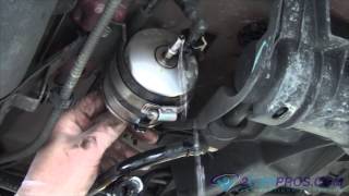
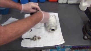
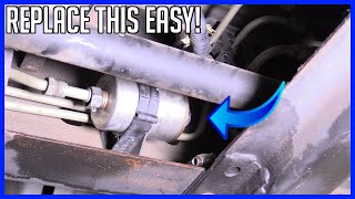
If blockage is suspected, replace the in-line fuel filter and retest.
If all the above fails to identify the issue, then remove tank.
Replace fuel pump module and fuel transfer pump (transfer fuel pump) assembly. (See Workshop Manual JTIS, CD ROM, section: 310-01, SRO 19.45.21). The pump may be worn, the filters may be heavily contaminated, or there may be a leak in the internal pipe work. Clean and flush any heavy contamination in the fuel tank.
ENGINE STARTING PROBLEMS
Ensure that there is adequate fuel in the tank.
Carry out fuel transfer check as described on page 5 in this bulletin.
Check fuel rail pressure with suitable calibrated fuel wet gauge during cranking or by using Datalogger on the WDS by monitoring fuel pump duty cycle, and fuel rail pressure sensor signals.
The pressure should rise rapidly to nominal rail pressure within two seconds. It is normal for the pressure to drop to zero when engine is switched 'OFF' over long periods. This does not indicate a component failure.
If there is pressure during cranking then the engine should start.
If there is no pressure when cranking, suspect an electrical or physical failure has occurred, or the supply has been interrupted by the vehicle systems.
If fault is still apparent, carry out following checks:
Check inertia switch is in the 'down' position.
Check that the Passive Anti Theft system (PATS) is proving out (See Technical Bulletin XT419-02 ) to ensure the immobilizer is not inhibiting fueling.
NOTE:If vehicle is cranking then the PATS is OK.
Use WDS guided diagnostics, to perform a complete function test on the fuel pump, to investigate the fuel pump and associated wiring.
Check the function of pump controller module by using a module from a known good vehicle.
Check for kinks or damage to the pipes, which may cause a restriction.
If blockage suspected replace the in line fuel filter and retest.
If fault still apparent, remove the tank and inspect parts for leaks in the internal pipe work and ensure that all connections are made and cross-tank lines are not twisted around each other when connected to transfer fuel pump. If no faults are found change the fuel pump module.
If fuel pressure is present then the vehicle may have been incorrectly fuelled with diesel, or there may be a quantity of water in the fuel. Determine this by draining some fuel into a container from the fuel rail Schrader valve, water will form 'puddles' at the bottom of the container. If there is a significant amount then drain and clean the fuel tank.
If fuel pressure is present and the vehicle is cranking, but refuses to start, there is most likely a problem elsewhere. Use WDS to interrogate the ECM for DTCs. Refer to Technical Bulletin XT303-04, engine management diagnostic flowcharts and also check injector functionality.
ENGINE STOPS WITH FUEL INDICATED IN THE FUEL TANK
If the engine stops when there is still fuel indicated in the fuel tank then there may be a fault with the internal transfer system.
Check for instrument cluster DTC B2879 that indicates a failure to transfer fuel.
Carry out following checks:
Check that transfer pipes are connected to the transfer fuel pump (internal to tank), disconnect and check that there are no splits in the small-bore pipe, reconnect and retest to verify.
Ensure the 2 mm hole is in the large bore pipe connected to the jet pump, if not carry out the procedure in Technical Bulletin XT310-01. Retest to verify.
The float arm is free to move retest to verify.
The alignment arrows on the module line up (within 10 degrees of the marks on the tank molding) retest to verify.
Check if the jet is blocked by blowing down the narrow bore inlet to the transfer fuel pump module (low pressure, DO NOT use airline). If contaminated do not attempt to clear blockage, as fault will recur. Replace transfer fuel pump assembly.
If DTC B2879 is still logged and fault is apparent, replace transfer fuel pump assembly.
If no DTC is logged and fault is still apparent, carry out fuel transfer check. Refer to FUEL TRANSFER CHECK.
DIAGNOSTIC CODE FLAGGED FOR EVAP SYSTEM GROSS LEAK
Refer to Technical Bulletin XT303-03 for in-depth EVAP leak diagnostics.
Locate the leak using approved EVAP emissions system test equipment.
SENDER UNIT OPEN/SHORT CIRCUIT
Use WDS to interrogate the ECM for DTC P0460 (fuel level sensor(s) circuit range/performance) and interrogate the Instrument Cluster for DTCs B1202, B1204 (fuel level sensor 1 circuit fault), B2627, B2628 (fuel level sensor 2 circuit fault).
If any DTCs are logged, carry out the associated guided diagnostic routine.
Remove the sender units from the tank and check the resistance through the range.
The resistance will vary between the two readings below.
Fuel level sensor resistance empty is 15 ohms. Fuel level sensor resistance at full is 160 ohms.
NOTE:It is possible that the sensors may become contaminated in a certain part of the mechanism, which may cause an open circuit at a certain fuel level.
DIFFICULTY REFUELING VEHICLE
If the complaint is intermittent the fault could be with the delivery nozzle at the gas station.
If the complaint is consistent then there may be a blockage in the vent system.
The canister close valve or filter may have some level of blockage. Suspect EVAP DTC P0446 to be logged (refer to Technical Bulletin XT303-03 ).
The canister may be full of water (wading) or there may be snow pack or ice around the canister outlet or carbon canister filter. Check for obstructions in filler neck/pipe (a foreign object, etc.) And for any damage.
Check that the correct filler neck is fitted:
Japanese market vehicles have a BLACK plastic insert within the filler neck.
Vehicles in all other markets have a GREY plastic insert.
Replace the filler neck assembly if the incorrect color is fitted.
Check that the customer is aware of the filling guidelines in the pocket manual in order that they optimize nozzle position. If the nozzle is not allowed to rest on the guide during filling, fill issues will occur due to the precise positioning required for the on board vapor recovery system.
FUEL SMELLS
Fuel smell may be due to a physical leak from any part of the fuel system.
Check all joints for leaks and seepage marks. If available use a HC sniffer around the high-pressure system to identify leak sources.
Check the outlet and inlet pipe connections to purge valve, and interrogate the ECM for purge valve DTCs as an inoperative purge valve may lead to vapor smells.
Check for leaks in the EVAP system using approved EVAP emissions system test equipment.
NOTE:It is important that the green seals and metal spacer ring are correctly reinstalled on the tank should the modules be removed for inspection. The seals should be replaced and petroleum jelly used to lubricate the locking ring on reassembly.
Check that the cap has been properly installed and that the customer is aware that it should be tightened to 'three clicks'.
FUEL PUMP NOISE
The fuel pump module should only be changed if the issue has been clearly identified as the pump.
NOTE:A certain amount of 'swishing' from the tank is normal as fuel is transferred around the fuel modules.
NOTE:The vehicle will idle for limited time if the fuel pump is disconnected.
To verify that the issue is the fuel pump, disconnect main tank harness while vehicle is running, if noise stops, change fuel pump module.
Ensure WDS is used to clear any DTCs this test procedure has caused, as disconnecting the main tank harness will cause DTCs to log.
FUEL TRANSFER CHECK
By entering the test mode in the Instrument Cluster, it is possible to view the individual sender values of the fuel pump module and the transfer fuel pump.
The test is to drive the vehicle in a tight, right hand bend to transfer fuel from the fuel pump module side to the transfer fuel pump side, then bringing the vehicle to rest and watch the transfer fuel pump sender value reduce over approx. 3 minutes.
WARNING:Use extreme care when carrying out the fuel transfer not to endanger other road users or infringe on road traffic regulations.
Ensure vehicle has between 1/4 and a 1/3 tank of fuel as indicated by the fuel gauge.
Enter Instrument Cluster Test Mode as follows:
With Ignition 'OFF' hold in the trip button on the indicator stalk and then turn ignition to 'ON' - position II.
Continue to hold the trip button in until 'TEST' appears on the cluster display.
Release the trip button.
Press the trip button to scroll through the available tests until you reach F2 XXX - this is the sender value of the transfer fuel pump.
Start the engine by turning the ignition to crank.
Note the value of F2 at idle. Value must read over 60, if not follow steps as in (4-6).
Drive the vehicle in a tight, right hand bend to transfer fuel from the Fuel pump module side to the transfer fuel pump side of the fuel tank, and then bring the vehicle to rest and watch the transfer fuel pump sender value reduce over approx 3 minutes.
If the value of F2 decreases to a value of approximately 28 to 29 this indicates that fuel is transferring.
If the value does not decrease, change the transfer fuel pump assembly.
If the F2 value displayed is 255 suspect an open/short circuit through the sender.
DRIVE CYCLE FOR 'GREEN' ECM
This procedure should be performed to enable ECM to relearn fuel metering adaptive values.
Due to component tolerance and wear during the normal running of a vehicle, fuel metering and air requirements for an engine will vary over time. The ECM has the ability to adapt to this variation by learning the level of compensation that is required. These compensation values are referred to as adaptive values.
If the vehicle battery is disconnected, all adaptive values held in the ECM memory will be lost (i.E. Set to zero); the ECM is then referred to as 'Green'. To enable the engine to run correctly and for the evaporative purge system to function, the ECM must 'relearn' these adaptive values. There are four areas or sites that need to be relearned.
This guide is intended to assist with the process of readapting the ECM without the need for any additional equipment, e.G. WDS unit.
Green ECM drive cycle
Idle vehicle until fully warm. Coolant temperature gauge just below mid point (48-50%).
Let engine idle for a further three minutes minimum. (Site 1)
Drive the vehicle, with the air conditioning off, on level road using a constant throttle (use speed control) for at least 60 seconds, in the following gears, at the stated engine speeds for sites 1, 2, 3 and 4 in table 1.
Return to rest and leave the vehicle idling for 60 seconds.
SPONSORED LINKS
Sunday, March 28th, 2010 AT 6:10 AM