I also have the manual, I will send it via email, just in case yours is incomplete!
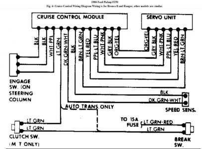
AMPLIFIER TEST "ON" Circuit Test, All Other Models 1. Turn ignition on, and connect a voltmeter between ground and Lt. Blue/Black wire at amplifier 6-way connector. Voltmeter should read 12 volts when "ON" switch in steering wheel is depressed and held. If no voltage is present, see the HORN RELAY CIRCUIT TEST and the CONTROL SWITCH TEST . 2. Release "ON" button. A 7.8-volt reading should remain on voltmeter, indicating "ON" circuit is engaged. If voltage does not remain, check for ground at amplifier, fuse and/or circuit breaker. Insert a known good amplifier and recheck "ON" circuit if necessary. "OFF" Circuit Test 1. With ignition on, and voltmeter connected to ground and Lt. Blue/Black wire at amplifier 6- way connector, depress "OFF" switch on steering wheel. Voltage should drop to zero, indicating "ON" circuit is de-energized. 2. If voltage does not drop to zero, perform CONTROL SWITCH TEST . If switches test good, install a known good amplifier and retest. "SET-ACC" Circuit Test 1. With ignition on, connect voltmeter leads to ground and to Lt. Blue/Black wire connector at amplifier. Depress "ON" switch, then hold "SET-ACC" button on steering wheel. 2. Voltmeter should read approximately 4.5 volts. Rotate steering wheel, and watch voltmeter for variation. If voltage varies more than .5 volts, perform CONTROL SWITCH TEST . "COAST" Circuit Test 1. With ignition on, connect voltmeter leads to ground and to Lt. Blue/Black wire connector at amplifier. Depress "ON" switch and hold down "COAST" button on steering wheel. 2. Voltmeter should read approximately 1.5 volts. If all functions check good, perform SERVO ASSEMBLY TEST . Insert a known good amplifier, and recheck system if necessary. "RESUME" Circuit Test 1. With ignition on, connect voltmeter leads to ground and to Lt. Blue/Black wire connector at CAUTION: DO NOT use a test light to perform amplifier tests, as excessive current draw will damage electronic components. Use only a voltmeter of 5000 ohm/volt rating or higher. NOTE: DO NOT substitute a new amplifier until actuator coils have been tested. See SERVO ASSEMBLY TEST . amplifier. Depress "ON" switch and then hold "RESUME" switch. Voltmeter should indicate approximately 6.5 volts. 2. If all functions are okay, perform SERVO ASSEMBLY TEST . Insert a known good amplifier, and recheck system if necessary. HORN RELAY CIRCUIT TEST All Except Aerostar, Bronco II & Ranger 1. Locate Yellow wire on Vans or Yellow/Lt. Blue dot wire on Bronco and Pickups at connector "X". Check for battery voltage on pin side of connector. See Fig. 3 . 2. Locate Blue/Yellow stripe wire on Vans or Dk. Blue wire on Bronco and Pickups at connector "Y". Check for battery voltage on socket side of connector. With voltmeter still connected to socket, depress horn switch. 3. Horn should sound, and voltmeter should indicate zero volts. If voltmeter still indicates battery voltage when horn switch is depressed, check horn switch or steering column wiring for an open circuit. Fig. 3: Wiring Diagram of Ford Cruise Control System Diagram for Van models shown. 4. To by-pass horn switch and check horn relay, momentarily ground Blue/Yellow wire on Vans or Dk. Blue wire on Bronco and Pickups on socket side of connector "Y". 5. If horn still does not sound, check Yellow/Green stripe wire on Vans or Yellow/Lt. Green wire on Bronco and Pickups at connector "X" for battery voltage while relay is activated. If battery voltage is present when relay is activated, an open circuit is present between connector "X" and horn. 6. If battery voltage is present in step 1) and horn relay failed to operate in step 3), replace relay. CLUTCH SWITCH TEST Vehicles With M/T 1. Make sure that clutch switch is depressed (switch closed) when clutch pedal is released, as cruise control will not operate unless this condition exists. Correct if necessary, before performing test. 2. Disconnect clutch switch connector from speed control harness connector, and connect an ohmmeter to switch connector terminals. With clutch pedal released and switch plunger depressed (switch closed), resistance should be less than 5 ohms. NOTE: Electrical connectors must remain connected during horn relay testing. NOTE: Switch operates magnetically. DO NOT use magnetized tools near switch. Use only a voltmeter of 5000 ohm/volt rating or higher to test switch. Test lamp will not indicate switch condition. 3. With clutch pedal depressed and switch plunger fully extended (switch open), resistance should be infinity (open circuit). BRAKE LIGHT SWITCH TEST 1. Check for stop light operation with a maximum brake pedal effort of 6 lbs. (2.7 kg). Check brake pedal actuation and stop light switch if pedal effort required is excessive. 2. If stop lights operate correctly, check battery voltage at 6-way connector Black/Green wire on Vans and White/Purple stripe wire on Bronco and Pickups. 3. Depress pedal until stop lights are on, and check voltage at 6-way connector Red/Black wire on Vans and Lt. Green wire on Bronco and Pickups. If voltage readings differ by more than 1.5 volts, high resistance exists in stop light circuit and must be corrected. 4. Check stop light switch, supply circuit, fuses and bulbs for correct operation, if stop lights do not work. VACUUM DUMP VALVE TEST 1. Vacuum dump valve should be checked whenever brake application does not release speed control. Disconnect vacuum hose from dump valve to servo, at servo unit. Connect hand vacuum pump to hose and pump up a vacuum. 2. If vacuum cannot be obtained, hose or dump valve leaks and should be replaced. Depress brake pedal. Vacuum should be released. If not, adjust or replace dump valve. VACUUM RESERVOIR TEST Diesel Engines Only 1. Locate vacuum reservoir on Left or Right fender. Disconnect vacuum hose at servo and connect a vacuum gauge with a minimum range of 0-25 in. Hg. Start engine and observe vacuum gauge. 2. Vacuum should be approximately 23 in. Hg., but not less than 20 in. Hg. If reading is not within specifications, check for leaking vacuum hose or faulty vacuum pump. 3. Turn engine off after vacuum has stabilized above 20 in. Hg. Vacuum should hold steady. After 24 hours, vacuum should be a minimum of 15 in. Hg. If vacuum fails to hold, replace vacuum reservoir. NOTE: This test should be performed whenever brake application will not disengage speed control. On vehicles with M/T, ensure that clutch switch is working properly before performing this test.
Wednesday, August 11th, 2010 AT 2:46 AM